
Page 42 - Process Equipment and Plant Design Principles and Practices by Subhabrata Ray Gargi Das
P. 42
38 Chapter 2 Heat transfer processes in industrial scale
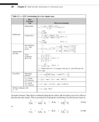
Table 2.3 εLNTU relationships for a few simple cases
Heat
Exchanger
Type Effectiveness Relation
Parallel Flow 1 exp ½ NTUð1 þ C r Þ
for C r s1
ε ¼
1 þ C r
NTU
for C r ¼ 1
1 þ NTU
ε ¼
Double pipe
Counter Flow
1 exp ½ NTUð1 C r Þ
for C r < 1
ε ¼
1 C r exp ½ NTUð1 C r Þ
NTU
for C r ¼ 1
1 þ NTU
ε ¼
One shell pass, 2 q ffiffiffiffiffiffiffiffiffiffiffiffiffiffi 3 1
2
2,4,..tube q ffiffiffiffiffiffiffiffiffiffiffiffiffiffi 1 þ exp NTU 1 þ C r
6 2 7
passes ε ¼ 2 6 1 þ C r þ 1 þ C r ffiffiffiffiffiffiffiffiffiffiffiffiffiffi 7
4 q 2 5
1 exp NTU 1 þ C
Standard Shell r
and Tube
N-2N 1 ε C r N
exchangers 1
1 ε
N¼2,.. etc. ε ¼ N for C r < 1
1 ε C r
C r
1 ε
Nε
for C r ¼ 1
ε ¼
1 þðN 1Þε
ε ¼ Effectiveness for 1-2 exchanger with same C r and (1/N) times the
NTU value
Cross Flow Both fluids ε ¼ 1 exp NTU 0:22 exp C r NTU 0:78 1
unmixed C r
C max mixed 1
C min unmixed ε ¼ C r ½1 expf1 C r ð1 expð NTUÞÞg
C min mixed
C max unmixed ε ¼ 1 exp½ ð1 =C r Þf1 expð C r NTUÞg
All heat exchangers with
C r ¼ 0 ε ¼ 1 expð NTUÞ
fin metal resistance. Since heat is conducted along the fin surface, the fin surface area is less effective
than the bare tube surface. This is accounted for in design by considering a fin effectiveness factor E f .
1 1 1
R w A h (2.14a)
¼ þ þ
U h A h h h E fh A h h c E fc A c
or
1 1 1
R w A c (2.14b)
¼ þ þ
U c A c h h E fh A h h c E fc A c