
Page 44 - Process Equipment and Plant Design Principles and Practices by Subhabrata Ray Gargi Das
P. 44
40 Chapter 2 Heat transfer processes in industrial scale
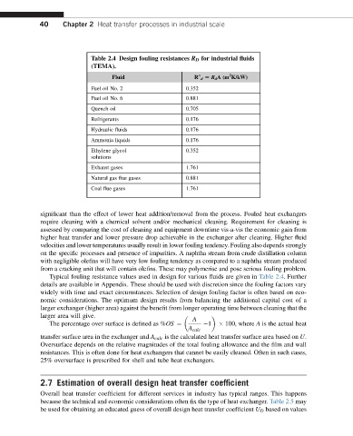
Table 2.4 Design fouling resistances R D for industrial fluids
(TEMA).
2
Fluid R d [ R d A(m K/kW)
00
Fuel oil No. 2 0.352
Fuel oil No. 6 0.881
Quench oil 0.705
Refrigerants 0.176
Hydraulic fluids 0.176
Ammonia liquids 0.176
Ethylene glycol 0.352
solutions
Exhaust gases 1.761
Natural gas flue gases 0.881
Coal flue gases 1.761
significant than the effect of lower heat addition/removal from the process. Fouled heat exchangers
require cleaning with a chemical solvent and/or mechanical cleaning. Requirement for cleaning is
assessed by comparing the cost of cleaning and equipment downtime vis-a-vis the economic gain from
higher heat transfer and lower pressure drop achievable in the exchanger after cleaning. Higher fluid
velocities and lower temperatures usually result in lower fouling tendency. Fouling also depends strongly
on the specific processes and presence of impurities. A naphtha stream from crude distillation column
with negligible olefins will have very low fouling tendency as compared to a naphtha stream produced
from a cracking unit that will contain olefins. These may polymerise and pose serious fouling problem.
Typical fouling resistance values used in design for various fluids are given in Table 2.4. Further
details are available in Appendix. These should be used with discretion since the fouling factors vary
widely with time and exact circumstances. Selection of design fouling factor is often based on eco-
nomic considerations. The optimum design results from balancing the additional capital cost of a
larger exchanger (higher area) against the benefit from longer operating time between cleaning that the
larger area will give.
A
1 100, where A is the actual heat
The percentage over surface is defined as %OS ¼
A calc
transfer surface area in the exchanger and A calc is the calculated heat transfer surface area based on U.
Oversurface depends on the relative magnitudes of the total fouling allowance and the film and wall
resistances. This is often done for heat exchangers that cannot be easily cleaned. Often in such cases,
25% oversurface is prescribed for shell and tube heat exchangers.
2.7 Estimation of overall design heat transfer coefficient
Overall heat transfer coefficient for different services in industry has typical ranges. This happens
because the technical and economic considerations often fix the type of heat exchanger. Table 2.5 may
be used for obtaining an educated guess of overall design heat transfer coefficient U D based on values