
Page 46 - Process Equipment and Plant Design Principles and Practices by Subhabrata Ray Gargi Das
P. 46
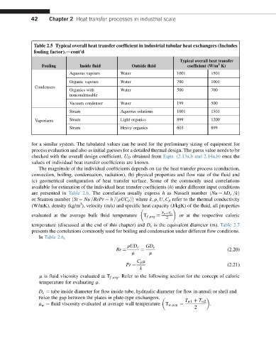
42     Chapter 2 Heat transfer processes in industrial scale


              Table 2.5 Typical overall heat transfer coefficient in industrial tubular heat exchangers (Includes
              fouling factor).dcont’d
                                                                       Typical overall heat transfer
                                                                                      2
                 Fouling        Inside fluid         Outside fluid          coefficient (W/m K)
                            Aqueous vapours     Water                 1001         1501
                            Organic vapours     Water                 700          1001
               Condensers
                            Organics with       Water                 500          700
                            noncondensable
                            Vacuum condenser    Water                 199          500
                            Steam               Aqueous solutions     1001         1501
               Vaporisers   Steam               Light organics        899          1200
                            Steam               Heavy organics        603          899


             for a similar system. The tabulated values can be used for the preliminary sizing of equipment for
             process evaluation and also as initial guesses for a detailed thermal design. The guess value needs to be
             checked with the overall design coefficient, U D obtained from Eqns. (2.13a,b and 2.14a,b) once the
             values of individual heat transfer coefficients are known.
                The magnitude of the individual coefficients depends on (a) the heat transfer process (conduction,
             convection, boiling, condensation, radiation), (b) physical properties and flow rate of the fluid and
             (c) geometrical configuration of heat transfer surface. Some of the commonly used correlations
             available for estimation of the individual heat transfer coefficients (h) under different input conditions

             are presented in Table 2.6. The correlation usually express h as Nusselt number ðNu ¼ hD e =kÞ
             or Stanton number ðSt ¼ Nu =RePr ¼ h =ðrUC p ÞÞ where k; r; U; C p refer to the thermal conductivity
                                3
             (W/mK), density (kg/m ), velocity (m/s) and specific heat capacity (J/kgK) of the fluid, all properties

             evaluated at the average bulk fluid temperature     T fi þT fo  or at the respective caloric
                                                                  2
                                                         T f ;avg ¼
             temperature (discussed at the end of this chapter) and D e is the equivalent diameter (m). Table 2.7
             presents the correlations commonly used for boiling and condensation under different flow conditions.
                In Table 2.6,
                                                   rUD e  GD e
                                                                                          (2.20)
                                                    m      m
                                              Re ¼      ¼
                                                      C p m
                                                                                          (2.21)
                                                        k
                                                  Pr ¼
                m is fluid viscosity evaluated at T f;avg . Refer to the following section for the concept of caloric
                temperature for evaluating m.
                D e ¼ tube inside diameter for flow inside tube, hydraulic diameter for flow in annuli or shell and
                twice the gap between the plates in plate-type exchangers.
                                                                         T w1 þ T w2
                m ¼ fluid viscosity evaluated at average wall temperature  T w;avg ¼  .
                 w
                                                                             2