
Page 66 - Process Equipment and Plant Design Principles and Practices by Subhabrata Ray Gargi Das
P. 66
62 Chapter 3 Double pipe heat exchanger
Typically,themaximumallowabledesignpressuredropsinadouble-pipeheatexchangerin0.7 kg/cm 2
for both inner and outer pipes. If the calculated pressure drop exceeds the allowable limit, the designer
needs to select a larger pipe diameter or decide to connect sections in parallel or a combination of series
and parallel. The flow with a higher volumetric flow rate is usually sent to the side with a higher flow
cross-sectional area.
3.3 Series-parallel configuration of hairpins
Pressure drop constraint in double pipe exchanger can often be met by dividing only the specific stream
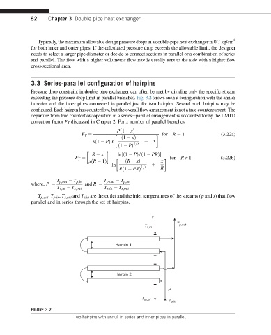
exceeding the pressure drop limit in parallel branches. Fig. 3.2 shows such a configuration with the annuli
in series and the inner pipes connected in parallel just for two hairpins. Several such hairpins may be
configured. Each hairpin has counterflow, but the overall flow arrangement is not a true countercurrent. The
departure from true counterflow operation in a serieseparallel arrangement is accounted for by the LMTD
correction factor F T discussed in Chapter 2. For x number of parallel branches
for R ¼ 1 (3.22a)
Pð1 xÞ
F T ¼
ð1 xÞ
xð1 PÞln x
1=x þ
ð1 PÞ
R x ln½ð1 PÞ=ð1 PRÞ
for Rs1 (3.22b)
x
F T ¼
ðR xÞ
xðR 1Þ
ln þ
1=x R
Rð1 PRÞ
T p;out T p;in T p;out T p;in
where, P ¼ and R ¼
T s;in T s;out T s;in T s;out
T p,out , T p,in , T s,out and T s,in are the outlet and the inlet temperatures of the streams (p and s) that flow
parallel and in series through the set of hairpins.
s
T
T s,in p,out
Hairpin 1
Hairpin 2
P
T s,out T p,in
FIGURE 3.2
Two hairpins with annuli in series and inner pipes in parallel.