
Page 68 - Process Equipment and Plant Design Principles and Practices by Subhabrata Ray Gargi Das
P. 68
64 Chapter 3 Double pipe heat exchanger
IF (abs((f o,new e f o )/f o,new ) < 0.02) and (abs((f o,new e f o )/f o,new ) < 0.02) THEN
GO TO Step 14
ELSE
GO TO Step 12
END
ELSE
Calculate T w from Eq.3.8 and proceed to calculate h i from Eq. 3.6.
GO TO Step 14
END
14. Calculate U D (Eq. 3.3). Calculate LMTD using F T from Eq. 3.22 if series-parallel configuration
is chosen, else LMTD to be calculated directly from {T h,in ,T h,out ,T c,in ,T h,out ,}.
15. Calculate A o (Eq. 3.1). L total ¼ A o /(pD i,o ), N HP ¼ L total /(2L std ); Round off L total to next higher
value of L std so that there are integral number of hairpins.
16. Calculate f i corresponding to Re i (Eq. 3.16). Calculate D e ’(Eq. 3.13c). Calculate Re o
(Eq. 3.15b). Calculate f o corresponding to Re o (Eq. 3.16 def).
17. Calculate DH f,o (Eq. 3.18a), DH f,o,bend (Eq. 3.19) and DH n (Eq. 3.20)
Calculate DP o (Eq. 3.21a).
Calculate DH f,i (Eq. 3.18b). Calculate DP i (Eq. 3.21b).
18. IF DP i > DP i,max THEN
Switch fluids and check for pressure drop.
IF even after switching fluids, the pressure drop limits are exceeded THEN
connect annuli in parallel and tubes in series. Recalculate F T using Eq. 3.22.
Go to step 9.
END
ELSE
Print Design output and fill up the rest of the form shown in Table 3.1.
END
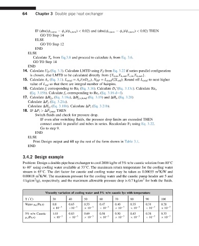
3.4.2 Design example
Problem: Design a double-pipe heat exchanger to cool 2000 kg/hr of 5% w/w caustic solution from 80 C
to 40 using cooling water available at 33 C. The maximum return temperature for the cooling water
2
stream is 45 C. The dirt factor for caustic and cooling water may be taken as 0.00035 m K/W and
2
0.00018 m K/W. The maximum pressure for the cooling water and the caustic pump header are 5 and
2
2
4kg/cm (g), respectively, and the maximum allowable pressure drop is 0.7 kg/cm for both the fluids.
Viscosity variation of cooling water and 5% w/w caustic lye with temperature
T( C) 30 40 50 60 70 80 90 100
Water m w (Pa.s) 0.8 0.65 0.55 0.47 0.40 0.35 0.31 0.28
10 3 10 3 10 3 10 3 10 3 10 3 10 3 10 3
5% w/w Caustic 1.03 0.83 0.69 0.58 0.50 0.43 0.38 0.33
m c (Pa.s) 10 3 10 3 10 3 10 3 10 3 10 3 10 3 10 3