
Page 73 - Process Equipment and Plant Design Principles and Practices by Subhabrata Ray Gargi Das
P. 73
70 Chapter 4 Shell and tube heat exchanger
closure fixed at this end is called the ‘stationary head’ or ‘channel’. Tube sheet at the other end
mayormay notbefixedtothe shell. Exchangers with stationary tube sheets at both ends are fixed
tube exchangers. These are cheaper and easy to construct but cause large thermal stresses on the
tubes and the shell.
To avoid high stresses, the more expensive and difficult to construct options namely floating head
exchangers or U-tube exchangers are opted for a large difference in temperature between the shell-side
fluid and the tube-side fluid. In floating head exchangers, the differential expansion of the shell and the
tube bundle is accommodated by fixing the tube sheet to the shell cover at one end only. This
arrangement (floating head) allows relative longitudinal movement due to thermal expansion between
the shell and the tubes. The shell at the floating head end is closed by a shell cover. Another way to
accommodate the differential expansion is to use ‘U’ tubes (‘U-tube exchangers’) that allow free
expansion and contraction of the individual tubes within the shell. The U-tube exchangers have only
one (stationary) tube sheet. In some cases, exchanger shell may have an integrated expansion joint.
This is less popular but is found in gas service exchangers in steel plants.
Tube-side fluid enters and exits through nozzles fitted on the heads, while nozzles on the shell allow
for entry and exit of the shell-side fluid.
Tubes
In most applications, plain tubes are used. However, when additional surface area is required to
compensate for low heat transfer coefficient on the shell-side, low finned tubing is used. Low fin
height maintains reasonably high fin efficiency and provides around two to three times the surface
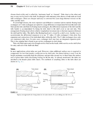
area of plain tubes while decreasing fouling on the fin side. As already mentioned, the tubes are
attached to the header plate (tube sheet). Two methods of attaching tubes to the tube sheet are
shown in Fig. 4.1.
( A ) T u b s e h e t e ( B ) T u b s e h e t e
Tube wall Tube wall
Ferrule
Turning
slot
Groove Packing
FIGURE 4.1
Typical arrangements for fixing tubes to the tube sheet: (A) tube rolling and (B) ferrule.