Page 69 - Process Equipment and Plant Design Principles and Practices by Subhabrata Ray Gargi Das
P. 69

3.4 Design illustration  65


               Solution

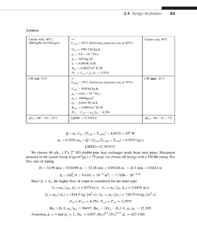
                 Caustic inlet, 80 C,   /                                       Caustic exit, 40 C


                 2000 kg/hr (0.5556 kg/s)  T c,avg ¼ 60 C(Following properties are at 60 C)


                                        C p;c ¼ 3983:2kJ=kg.K
                                        m c ¼ 5:8   10  4  Pa.s
                                                    3
                                        r c ¼ 1055 kg=m
                                        k c ¼ 0:688 W=m.K
                                                    2
                                        R d;c ¼ 0:00035 m .K=W

                                        Pr c ¼ C p;c   m c k c ¼ 3:3579
                 CW exit,33 C           )                                       CW inlet.33 C


                                        T w,avg ¼ 39 C(Following properties are at 39 C)


                                        C p;w ¼ 4185 kJ=kg.K
                                        m w ¼ 6:65   10  4  Pa.s
                                                    3
                                        r w ¼ 1000 kg=m
                                        k w ¼ 0:6541 W=m.K
                                                     2
                                        R d;w ¼ 0:00018 m :K=W

                                        Pr w ¼ C p;w   m w k w ¼ 4:254

                 DT 1 ¼ 80   45 ¼ 35 C  LMTD ¼ 17.3974 C                        DT 2 ¼ 40   33 ¼ 7 C


                                                                       4
                                     Q ¼ m c :C p;c : T c;in   T c;out ¼ 8.8515   10 W
                                m c ¼ 0:5555; m w ¼ Q = ðC p;w ðT w;out   T w;in Þ¼ 0.5555 kg=s
                                               LMTD ¼ 17.3974 C.

                  We choose 40 sch., 1.5 x2 ND double-pipe heat exchanger made from steel pipes. Maximum
                                         00
                                     00
                                             2
               pressure in the system being 6 kg/cm (g) (w75 psig), we choose all fittings with a 150 lbs rating. For
               this, size of piping,
                      D i ¼ 34.98 mm ¼ 0.03498 m; ¼ 52.48 mm ¼ 0.05248 m; ¼ 42.1 mm ¼ 0.0421 m
                                        2                4  2              4m 2
                                  A i ¼ pD =4 ¼ 9.6101   10  m ; ¼ 7.7106   10
                                        i
                  Since A i > A o , the higher flow of water is considered for the inner pipe
                             V i ¼ m w =ðr :A i Þ¼ 1:8375 m=s; V o ¼ m c =ðr :A o Þ¼ 0:6829 m=s
                                       w                          c
                                                   2                                2
                          G i ¼ m w =ðA i Þ¼ 1834:5kg= m :s ; G o ¼ m o =ðA o Þ¼ 720:5116 kg= m :s
                                       P r;t ¼ P r;w ¼ 4:254; P r;o ¼ P r;c ¼ 3:3579


                            Re t ¼ D i :V i :r =m ¼ 96497; Re o ¼ D i;o   D o :V o :r =m ¼ 12; 895
                                                                           c
                                                                        c
                                       w
                                          w
                                                          0:8    0:33
                                     o
                                                                     t
                            t
                  Assuming f ¼ 1 and f ¼ 1, Nu t ¼ 0:027:ðRe t Þ  :ðPr t Þ  :f ¼ 423:1341;
   64   65   66   67   68   69   70   71   72   73   74