
Page 75 - Process Equipment and Plant Design Principles and Practices by Subhabrata Ray Gargi Das
P. 75
72 Chapter 4 Shell and tube heat exchanger
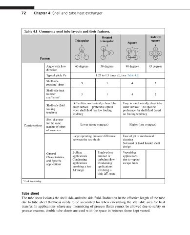
Table 4.1 Commonly used tube layouts and their features.
Rotated Rotated
Triangular triangular square
Square
Pattern
Angle with flow 60 degrees 30 degrees 90 degrees 45 degrees
direction
Typical pitch, P T 1.25 to 1.5 times D o (see Table 4.8)
Shell-side
a
pressure drop 3 1 4 2
Shell-side heat
transfer 3 1 4 2
coefficient a
Difficult to mechanically clean tube Easy to mechanically clean tube
Shell-side fluid outer surface e preferable option outer surface e no specific
fouling when shell fluid has low fouling preference for shell fluid based
tendency
tendency on fouling tendency
Shell diameter
for the same
Considerations number of tubes Lower (more compact) Higher (less compact)
of same size
Large operating pressure difference Ease of jet or mechanical
between the two fluids cleaning
Not used in fixed header sheet
design
Boiling Single-phase Vaporising
General
applications laminar or applications
Characteristics
Condensing turbulent flow due to vapour
and Specific
applications applications Condensing escape lanes
involving a low applications
DT range involving a
high DT range
a
1e4 decreasing.
Tube sheet
The tube sheet isolates the shell-side and tube-side fluid. Reduction in the effective length of the tube
due to tube sheet thickness needs to be accounted for when calculating the available area for heat
transfer. In applications where any intermixing of process fluids cannot be allowed due to safety or
process reasons, double tube sheets are used with the space in between those kept vented.