
Page 79 - Process Equipment and Plant Design Principles and Practices by Subhabrata Ray Gargi Das
P. 79
76 Chapter 4 Shell and tube heat exchanger
4.1.2 Heat exchanger installations and commissioning
When the exchanger being designed is a part of an existing process system, compatibility is of
utmost importance. If exchangers for similar services already exist in the plant, it is often better to
add one that can provide interchangeability or have common spares like tube bundle, tubes, etc.
Space for erection, operation and maintenance is also a major consideration. The space needs to have
drainage facility for proper and safe disposal of the drained fluids before maintenance. Utility
connections that are required for flushing, pressure testing, cleaning, etc., should be available.
Bypassing the shell side or the tube side of an exchanger is not usually desirable as this lead to low
flow through the equipment resulting in enhanced fouling. However, in large continuous plants, such
bypass and equipment isolation arrangements are provided for flexibility. This allows the heat ex-
changers to be decommissioned, cleaned and maintained, while the rest of the plant and equipment
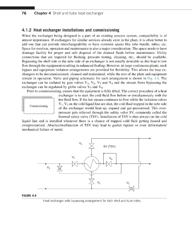
remain in operation. Valve and piping schematic for such arrangement is shown in Fig. 4.4.The
exchanger can be isolated by gate valves V 1 ,V 2 ,V 3 and V 4 and the stream flows bypassing the
exchanger can be regulated by globe valves V 5 and V 6 .
Prior to commissioning, ensure that the equipment is fully filled. The correct procedure of a heat
exchanger is to start the cold fluid flow before or simultaneously with the
hot fluid flow. If the hot stream continues to flow while the isolation valves
V 1 ,V 2 on the cold liquid line are shut, the cold fluid trapped in the tube side
Commissioning
of the exchanger would heat up, expand and get pressurised. This over-
pressure gets relieved through the safety valve SV, commonly called the
thermal safety valve (TSV). Installation of TSV is thus always on the cold
liquid line and is installed whenever there is a chance of trapped cold fluid getting heated and
overpressurised. Absence/malfunction of TSV may lead to gasket rupture or even deformation/
mechanical failure of metal.
V 4
SV (TSV)
V 1 V 2
V 6
V 3 V 5
FIGURE 4.4
Heat exchanger with bypassing arrangement for both shell and tube sides.