
Page 83 - Process Equipment and Plant Design Principles and Practices by Subhabrata Ray Gargi Das
P. 83
80 Chapter 4 Shell and tube heat exchanger
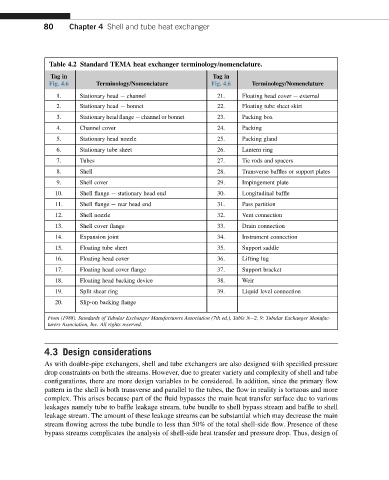
Table 4.2 Standard TEMA heat exchanger terminology/nomenclature.
Tag in Tag in
Fig. 4.6 Terminology/Nomenclature Fig. 4.6 Terminology/Nomenclature
1. Stationary head e channel 21. Floating head cover e external
2. Stationary head e bonnet 22. Floating tube sheet skirt
3. Stationary head flange e channel or bonnet 23. Packing box
4. Channel cover 24. Packing
5. Stationary head nozzle 25. Packing gland
6. Stationary tube sheet 26. Lantern ring
7. Tubes 27. Tie rods and spacers
8. Shell 28. Transverse baffles or support plates
9. Shell cover 29. Impingement plate
10. Shell flange e stationary head end 30. Longitudinal baffle
11. Shell flange e rear head end 31. Pass partition
12. Shell nozzle 32. Vent connection
13. Shell cover flange 33. Drain connection
14. Expansion joint 34. Instrument connection
15. Floating tube sheet 35. Support saddle
16. Floating head cover 36. Lifting lug
17. Floating head cover flange 37. Support bracket
18. Floating head backing device 38. Weir
19. Split shear ring 39. Liquid level connection
20. Slip-on backing flange
From (1988). Standards of Tubular Exchanger Manufacturers Association (7th ed.), Table Ne2, 9: Tubular Exchanger Manufac-
turers Association, Inc. All rights reserved.
4.3 Design considerations
As with double-pipe exchangers, shell and tube exchangers are also designed with specified pressure
drop constraints on both the streams. However, due to greater variety and complexity of shell and tube
configurations, there are more design variables to be considered. In addition, since the primary flow
pattern in the shell is both transverse and parallel to the tubes, the flow in reality is tortuous and more
complex. This arises because part of the fluid bypasses the main heat transfer surface due to various
leakages namely tube to baffle leakage stream, tube bundle to shell bypass stream and baffle to shell
leakage stream. The amount of these leakage streams can be substantial which may decrease the main
stream flowing across the tube bundle to less than 50% of the total shell-side flow. Presence of these
bypass streams complicates the analysis of shell-side heat transfer and pressure drop. Thus, design of