
Page 85 - Process Equipment and Plant Design Principles and Practices by Subhabrata Ray Gargi Das
P. 85
82 Chapter 4 Shell and tube heat exchanger
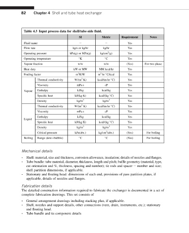
Table 4.3 Input process data for shell/tube-side fluid.
SI Metric Requirement Notes
Fluid name e e Yes
Flow rate kg/s or kg/hr kg/hr Yes
2
Operating pressure kPa(g) or MPa(g) kg/cm (g) Yes
Operating temperature K C Yes
Vapour fraction w/w w/w (Yes) For two phase
Heat duty kW or MW MM kcal/hr Yes
2
2
Fouling factor m K/W m hr C/kcal Yes
2
Thermal conductivity W/(m K) kcal/(m hr C) Yes
Viscosity mPa s cP Yes
Vapour Enthalpy kJ/kg kcal/kg Yes
Specific heat kJ/(kg K) kcal/(kg C) Yes
Density kg/m 3 kg/m 3 Yes
2
Thermal conductivity W/(m K) kcal/(m hr C) Yes
Viscosity mPa s cP Yes
Enthalpy kJ/kg kcal/kg Yes
Liquid
Specific heat kJ/(kg K) kcal/(kg C) Yes
Density kg/m 3 kg/m 3 Yes
2
Critical pressure kPa(abs.) kg/cm (abs.) (Yes) For boiling
Boiling Range (dewebubble) C C (Yes) For boiling
Mechanical details
- Shell: material, size and thickness, corrosion allowance, insulation; details of nozzles and flanges.
- Tube bundle: tube material, diameter, thickness, length and pitch; baffle geometry (material, type,
cut orientation and %, thickness, spacing and number); tie rods and spacer e number and size;
shell partition dimensions, if applicable.
- Stationary and floating head: dimensions of each end, provisions of pass partition plates, if
applicable, details of nozzles and flanges.
Fabrication details
The detailed construction information required to fabricate the exchanger is documented in a set of
complete fabrication drawings. This set consists of
- General arrangement drawings including stacking plan, if applicable.
- Shell, nozzles and support details, other connections (vent, drain, instruments, etc.); stationary
and floating head.
- Tube bundle and its component details