
Page 87 - Process Equipment and Plant Design Principles and Practices by Subhabrata Ray Gargi Das
P. 87
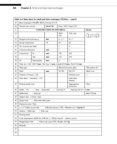
84     Chapter 4 Shell and tube heat exchanger


              Table 4.4 Data sheet for shell and tube exchanger (TEMA).dcont’d
               29  Heat exchanged 4300 kW; MTD corrected 19.9 C

                                                2
               30  Transfer rate, service  W/(m K)     Dirty: 930.7 Clean:1274
               31                 CONSTRUCTION OF ONE SHELL                     Sketch
               32                                      Shell     Tube side
                                                       side
               33  Design/vac/test pressure.g  bar     6 / /     6/ /
               34  Design temperature        C         85        85
               35  No. of passes per shell             1         2
               36  Corrosion allowance     mm          3         3
               37  Connections  In         mm          438       305
               38              Out         mm          154       255
               39  ID          Intermediate  mm        /-        /-

               40  Tube nos. 1106; OD 19 mm; Tks-Avg 1.2 mm; Length 4120 mm; Pitch 23.8 mm
               41  Tube type                           Material CS plain tubes  Tube pattern 60
               42  Shell                   mm          ID 950    OD 974         Shell cover -
               43  Channel or bonnet e CS                        Channel cover  e
               44  Tube sheet e stationary e CS                  Tube sheet     e
                                                                 floating
               45  Floating head cover                           Impingement    None
                                                                 protection
               46  Baffle e CS   ;  Type e Segmental  ; Cut(%d) 25  ; Spacing 395 (CeC) mm

               47  Baffle-long  ; Seal type  ;                                   Inlet 570 mm
               48  Support-tube U-bend; Type
               49  Bypass seal  ; Tube-tube sheet joint;
               50  Expansion joint; Type;
                                                                              2
                       2
               51  r   V @Inlet nozzle 640:  @Bundle entrance 1350; @Bundle exit 17 kg/(m s )
               52  Gaskets e Shell side  ; Tube side
               53  Floating head
               54  Code requirement ASME Sec VIII Div 1; TEMA class R e refinery service
               55  Weight/Shell 5300  ; Filled with water 8720; Bundle 3045 kg
               56  Remarks
               57
               58