
Page 92 - Process Equipment and Plant Design Principles and Practices by Subhabrata Ray Gargi Das
P. 92
4.4 Design e F T method 89
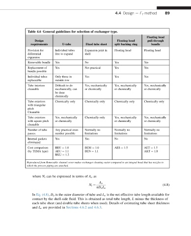
Table 4.6 General guidelines for selection of exchanger type.
Floating head
Design Floating head pull-through
requirements U-tube Fixed tube sheet split backing ring bundle
Provision for Individual tubes Expansion joint in Floating head Floating head
differential free to expand shell
expansion
Removable bundle Yes No Yes Yes
Replacement of Yes Not practical Yes Yes
bundle possible
Individual tubes Only those in Yes Yes Yes
replaceable outside row
Tube interiors Difficult to do Yes, mechanically Yes, mechanically Yes, mechanically
cleanable mechanically, can or chemically or chemically or chemically
be done
chemically
Tube exteriors Chemically only Chemically only Chemically only Chemically only
with triangular
pitch
Cleanable
Tube exteriors Yes, mechanically Chemically only Yes, mechanically Yes, mechanically
with square pitch or chemically or chemically or chemically
cleanable
Number of tube Any practical even Normally no Normally no Normally no
passes number possible limitations limitations limitations
Internal gaskets Yes Yes No No
eliminated
Cost comparison BEU ¼ 1.0 BEM ¼ 1.0 AES ¼ 1.5 AET ¼ 1.5
(by TEMA type) AEU ¼ 1.1 BEN ¼ 1.1 AKT ¼ 1.8
BKU ¼ 1.2
Reproduced from Removable channel cover makes exchanger cleaning easier compared to an integral head that has nozzles to
which the process piping are attached.
where N t can be expressed in terms of A o as
A o
(4.8)
N t ¼
pD o L e
In Eq. (4.8), D o is the outer diameter of tube and L e is the net effective tube length available for
contact by the shell-side fluid. This is obtained as total tube length, L minus the thickness of
each tube sheet (and double tube sheets when used). Details of estimating tube sheet thickness
and L e are provided in Sections 4.6.2 and 4.6.3.