
Page 93 - Process Equipment and Plant Design Principles and Practices by Subhabrata Ray Gargi Das
P. 93
90 Chapter 4 Shell and tube heat exchanger
CL in Eq. (4.7) accounts for the area of shell cross section required to accommodate one tube and
depends on the type of pitch chosen: It is 1 for 45 degrees and 90 degrees tube layout and 0.87 for
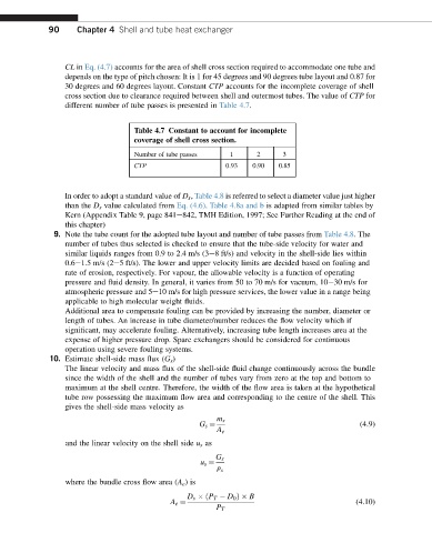
30 degrees and 60 degrees layout. Constant CTP accounts for the incomplete coverage of shell
cross section due to clearance required between shell and outermost tubes. The value of CTP for
different number of tube passes is presented in Table 4.7.
Table 4.7 Constant to account for incomplete
coverage of shell cross section.
Number of tube passes 1 2 3
CTP 0.93 0.90 0.85
In order to adopt a standard value of D s , Table 4.8 is referred to select a diameter value just higher
than the D s value calculated from Eq. (4.6). Table 4.8a and b is adapted from similar tables by
Kern (Appendix Table 9, page 841e842, TMH Edition, 1997; See Further Reading at the end of
this chapter)
9. Note the tube count for the adopted tube layout and number of tube passes from Table 4.8. The
number of tubes thus selected is checked to ensure that the tube-side velocity for water and
similar liquids ranges from 0.9 to 2.4 m/s (3e8 ft/s) and velocity in the shell-side lies within
0.6e1.5 m/s (2e5 ft/s). The lower and upper velocity limits are decided based on fouling and
rate of erosion, respectively. For vapour, the allowable velocity is a function of operating
pressure and fluid density. In general, it varies from 50 to 70 m/s for vacuum, 10e30 m/s for
atmospheric pressure and 5e10 m/s for high pressure services, the lower value in a range being
applicable to high molecular weight fluids.
Additional area to compensate fouling can be provided by increasing the number, diameter or
length of tubes. An increase in tube diameter/number reduces the flow velocity which if
significant, may accelerate fouling. Alternatively, increasing tube length increases area at the
expense of higher pressure drop. Spare exchangers should be considered for continuous
operation using severe fouling systems.
10. Estimate shell-side mass flux (G s )
The linear velocity and mass flux of the shell-side fluid change continuously across the bundle
since the width of the shell and the number of tubes vary from zero at the top and bottom to
maximum at the shell centre. Therefore, the width of the flow area is taken at the hypothetical
tube row possessing the maximum flow area and corresponding to the centre of the shell. This
gives the shell-side mass velocity as
m s
(4.9)
G s ¼
A e
and the linear velocity on the shell side u s as
G s
r s
u s ¼
where the bundle cross flow area (A e )is
D s ðP T D 0 Þ B
(4.10)
A e ¼
P T