Page 91 - Process Equipment and Plant Design Principles and Practices by Subhabrata Ray Gargi Das
P. 91

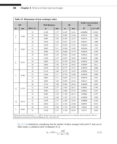
88     Chapter 4 Shell and tube heat exchanger


               Table 4.5 Dimensions of heat exchanger tubes.
                                                                            Inside cross-sectional
                  OD                     Wall thickness         ID                area
                                                                                        2
               in.   mm    BWG No.        in.       mm      in.    mm         ft 2    m 310 4
                              12         0.109      2.77   0.407   10.33   0.000903    0.8381
                              14         0.083      2.11   0.459   11.66    0.00115    1.068
               5    15.88
               8
                              16         0.065      1.65   0.495   12.57    0.00134    1.241
                              18         0.049      1.25   0.527   13.39    0.00151    1.408
                              12         0.109      2.77   0.532   13.51    0.00154    1.434
               3    19.05     14         0.083      2.11   0.584   14.83    0.00186    1.727
               4
                              16         0.065      1.65   0.620   15.75    0.00210    1.948
                              18         0.049      1.25   0.652   16.56    0.00232    2.154
                              12         0.109      2.77   0.657   16.69    0.00235    2.188
                              14         0.083      2.11   0.709   18.01    0.00274    2.548
               7    22.23
               8
                              16         0.065      1.65   0.745   18.92    0.00303    2.811
                              18         0.049      1.25   0.777   19.74    0.00329    3.060
                              10         0.134      3.40   0.732   18.59    0.00292    2.714
                              12         0.109      2.77   0.782   19.86    0.00334    3.098
               1    25.40
                              14         0.083      2.11   0.834   21.18    0.00379    3.523
                              16         0.065      1.65   0.870   22.10    0.00413    3.836
                              10         0.134      3.40   0.982   24.94    0.00526    4.885

               1 1  31.75     12         0.109      2.77   1.032   26.21    0.00581    5.395
                4
                              14         0.083      2.11   1.084   27.53    0.00641    5.953
                              16         0.065      1.65   1.120   28.45    0.00684    6.357
                              10         0.134      3.40   1.232   31.29    0.00828    7.690
                              12         0.109      2.77   1.282   32.56    0.00896    8.326
               1  1  38.10
                2
                              14         0.083      2.11   1.334   33.88    0.00971    9.015
                              10         0.134      3.40   1.732   43.99    0.0164     15.20
               2    50.80
                              12         0.109      2.77   1.782   45.26    0.0173     16.09
              Reproduced from Geankoplis, C. J., (2003). Transport processes and separation process principles (unit operations) (4th ed.).
              Reprinted by permission of Pearson Education, Inc., New York, NY.


                 Eq. (4.7) is obtained by considering that the number of tubes arranged with pitch P t that can be
                 fitted inside a cylindrical shell of diameter D s is
                                                         pD 2 s
                                            N t ¼ CTP          2                           (4.7)
                                                      4   CL   P
                                                               T
   86   87   88   89   90   91   92   93   94   95   96