
Page 95 - Process Equipment and Plant Design Principles and Practices by Subhabrata Ray Gargi Das
P. 95
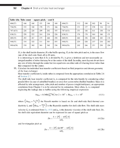
92     Chapter 4 Shell and tube heat exchanger


          Table 4.8a Tube count e square pitch.dcont’d
          686(27)     166    160    151    146    140    686(27)      112    108    102    98    94
          736(29)     193    188    178    174    166    736(29)      131    127    120    116   112
          787.4(31)   226    220    209    202    193    787.4(31)    151    146    141    138   131
          838(33)     258    252    244    238    226    838(33)      176    170    164    160   151
          889(35)     293    287    275    268    258    889(35)      202    196    188    182   176
          940(37)     334    322    311    304    293    940(37)      224    220    217    210   202
          990.6(39)   370    362    345    342    336    990.6(39)    252    246    237    230   224


                 D s is the shell inside diameter, B is the baffle spacing, P T is the tube pitch and m s is the mass flow
                 rate of the shell-side fluid, all in SI units.
                 It is interesting to note that if D s is divided by P T , it gives a fictitious and not necessarily an
                 integral number of tubes that may be at the centre of the shell. In reality, most layouts do not have
                 any row of tubes through the centre but two equal rows on either side of it having fewer tubes than
                 that computed for the centre.
             11. Calculate the individual heat transfer coefficients based on fluid properties and chosen geometry
                 of the heat exchanger.
                 Heat transfer coefficient h i inside tubes is computed from the appropriate correlation in Table 2.6
                 of Section 2.7.
                 The shell-side heat transfer coefficient h o is computed for the tube bundle by considering either
                 parallel flow (in case of unbaffled bundles) or cross flow across tubes (baffled bundles). Since it is
                 affected by tube arrangement, tube pitch and number of passes (single/multipass), an appropriate
                 correlation from Chapter 2 is to be selected for its estimation. Most often, h o is computed
                 neglecting the leakage due to baffles using the following empirical expression
                                                 1
                                             0:55          3              6
                                 Nu De ¼ 0:36Re  Pr s for 2   10 < Re De < 1   10         (4.11)
                                                 3
                                             De
                               h o  De
                                   Þ the Nusselt number is based on De and shell-side fluid thermal con-
                 where ðNu De ¼
                                 k s
                                      DeG s
                 ductivity k s and ðRe De ¼  Þ is the Reynolds number for shell-side flow. The shell-side mass
                                       m s
                 velocity G s is estimated from Eq. (4.9) and m is the dynamic viscosity of the shell-side fluid. De,
                                                     s
                 the shell-side equivalent diameter can be expressed in case of square pitch as
                                                       2    2
                                                 4   P   pD =4
                                                            o
                                                      T
                                                                                         (4.12a)
                                            De ¼
                                                       pD o
                 and for triangular pitch as
                                                    2          2
                                             4   P sin 60   pD =4

                                                   T           o
                                                                                         (4.12b)
                                         De ¼
                                                       pD o