
Page 89 - Process Equipment and Plant Design Principles and Practices by Subhabrata Ray Gargi Das
P. 89
86 Chapter 4 Shell and tube heat exchanger
For n number of shell passes,
1
1 RS n
1
1 S
When R s 1 S n ¼ 1
1 RS n
R
1 S
2
p ffiffiffiffiffiffiffiffiffiffiffiffiffiffi
R þ 1 ð1 S n Þ
ln
(4.1)
ðR 1Þ ð1 RS n Þ
and F T ¼ p ffiffiffiffiffiffiffiffiffiffiffiffiffiffi
2
R þ 1
ð2=S n Þ 1 R þ
ln p ffiffiffiffiffiffiffiffiffiffiffiffiffiffi
2
R þ 1
ð2=S n Þ 1 R
S
When R ¼ 1 S n ¼
1 þ nS S
p ffiffiffi S n
2
(4.2)
ð1 S n Þ
p ffiffiffiffiffiffiffiffiffiffiffiffiffiffi
and F T ¼ 2
R þ 1
ln p ffiffiffiffiffiffiffiffiffiffiffiffiffiffi
ð2=S n Þ 1 R þ
2
R þ 1
ð2=S n Þ 1 R
Subscript n refers to the number of shell passes. The expressions for F T are thus symmetric with
respect to fluid placement.
T c,out T h,in T c,out T h,in
T c,in T h,out T c,in T h,out
T h,in T h,in
T h,out
T c,out T c,out T h,out
T c,in T c,in
Flow path Flow path
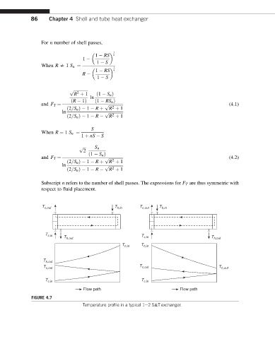
FIGURE 4.7
Temperature profile in a typical 1e2S&T exchanger.