
Page 78 - Process Equipment and Plant Design Principles and Practices by Subhabrata Ray Gargi Das
P. 78
4.1 Introduction 75
odd number of tube passes (3, 5, etc.) though permitted in design code (TEMA), is rarely used due to
their complicated construction and associated mechanical problems in fabrication and operation.
In case of single-tube pass configuration, the tube-side fluid flows through all the tubes in a shell in
the same direction, i.e., all tubes are fed from the front stationary head and
discharge into the rear end head. In multiple tube pass, there are separate
bunches of tubes where the tube-side fluid flows from the front to the rear
Pass partition plate
end and then back to the front head. This is achieved either by U tubes or
by pass partition plates designed integral to the stationary head and the rear
head. They guide the tube-side fluid to enter and exit specific bunch of
tubes thus ensuring long passage lengths within a fixed shell length. Each bunch contains almost the
same number of tubes to achieve same flow area per pass. Increasing the number of passes for the same
total number of tubes thus increases the tube-side velocity, turbulence and heat transfer coefficient.
Higher tube-side velocity also reduces fouling tendency. However, the increased velocity and addi-
tional turns (change in direction of fluid flow) significantly increase the tube-side pressure drop.
In case of a 1e2 exchanger, there will be pass partition plate only on the front end. The tube-side
fluid entry and exit nozzles are on opposite sides of the stationary head for even number of passes. The
number of tube passes is often limited by the allowable pressure drop and generally range from 1 to 10.
The standard design has one, two, or four tube passes. If a higher pressure drop is acceptable, it is
desirable to have fewer but longer tubes (reduced flow area and increased flow length). The cross flow
area (perpendicular to the flow direction in tubes) in the channel depends on the channel depth, and its
diameter is fixed by tube sheet diameter.
Shell passes
The path of the shell fluid may also require several reversal of direction to make the exchanger
compact. This is achieved by longitudinal baffles assembled integrated with the tube sheet. A single
longitudinal baffle ensures two passes for the fluid in a shell as can be seen in the ‘F’ type shell in
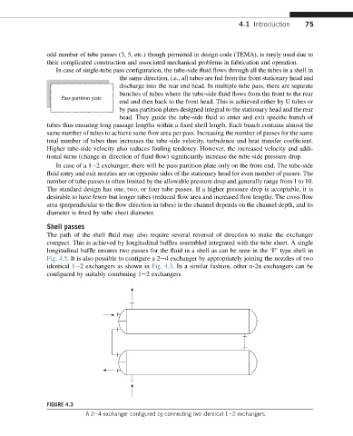
Fig. 4.5. It is also possible to configure a 2e4 exchanger by appropriately joining the nozzles of two
identical 1e2 exchangers as shown in Fig. 4.3. In a similar fashion, other n-2n exchangers can be
configured by suitably combining 1e2 exchangers.
FIGURE 4.3
A2e4 exchanger configured by connecting two identical 1e2 exchangers.