
Page 20 - Process Modelling and Simulation With Finite Element Methods
P. 20
Introduction to FEMLAB 7
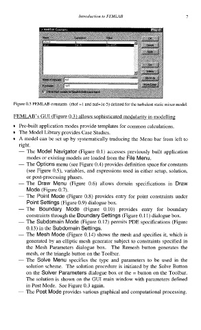
Figure 0.5 FEMLAB constants (rhof =1 and nuf=le-5) defined for the turbulent static mixer model.
J
Pre-built application modes provide templates for common calculations.
The Model Library provides Case Studies.
A model can be set up by systematically traducing the Menu bar from left to
right.
- The Model Navigator (Figure 0.1) accesses previously built application
modes or existing models are loaded from the File Menu.
- The Options menu (see Figure 0.4) provides definition space for constants
(see Figure OS), variables, and expressions used in either setup, solution,
or post-processing phases.
- The Draw Menu (Figure 0.6) allows domain specifications in Draw
Mode (Figure 0.7).
- The Point Mode (Figure 0.8) provides entry for point constraints under
Point Settings (Figure 0.9) dialogue box.
- The Boundary Mode (Figure 0.10) provides entry for boundary
constraints through the Boundary Settings (Figure 0.11) dialogue box.
- The Subdomain Mode (Figure 0.12) permits PDE specifications (Figure
0.13) in the Subdomain Settings.
- The Mesh Mode (Figure 0.14) shows the mesh and specifies it, which is
generated by an elliptic mesh generator subject to constraints specified in
the Mesh Parameters dialogue box. The Remesh button generates the
mesh, or the triangle button on the Toolbar.
- The Solve Menu specifies the type and parameters to be used in the
solution scheme. The solution procedure is initiated by the Solve Button
on the Solver Parameters dialogue box or the = button on the Toolbar.
The solution is shown on the GUI main window with parameters defined
in Post Mode. See Figure 0.3 again.
- The Post Mode provides various graphical and computational processing.