
Page 23 - Process Modelling and Simulation With Finite Element Methods
P. 23
10 Process Modelling and Simulation with Finite Element Methods
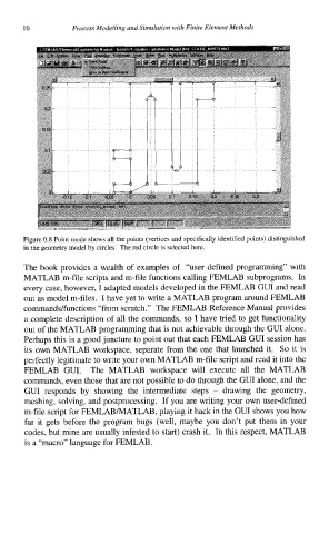
Figure 0.8 Point mode shows all the points (vertices and specifically identified points) distinguished
in the geometry model by circles. The red circle is selected here.
The book provides a wealth of examples of “user defined programming” with
MATLAB m-file scripts and m-file functions calling FEMLAB subprograms. In
every case, however, I adapted models developed in the FEMLAB GUI and read
out as model m-files. I have yet to write a MATLAB program around FEMLAB
commands/functions “from scratch.” The FEMLAB Reference Manual provides
a complete description of all the commands, so 1 have tried to get functionality
out of the MATLAB programming that is not achievable through the GUI alone.
Perhaps this is a good juncture to point out that each FEMLAB GUI session has
its own MATLAB workspace, separate from the one that launched it. So it is
perfectly legitimate to write your own MATLAB m-file script and read it into the
FEMLAB GUI. The MATLAB workspace will execute all the MATLAB
commands, even those that are not possible to do through the GUI alone, and the
GUI responds by showing the intermediate steps - drawing the geometry,
meshing, solving, and postprocessing. If you are writing your own user-defined
m-file script for FEMLABNATLAB, playing it back in the GUI shows you how
far it gets before the program bugs (well, maybe you don’t put them in your
codes, but mine are usually infested to start) crash it. In this respect, MATLAB
is a “macro” language for FEMLAB.