
Page 281 - Process Modelling and Simulation With Finite Element Methods
P. 281
268 Process Modelling and Simulation with Finite Element Methods
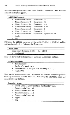
Pull down the options menu and select Add/Edit constants. The AddEdit
constants dialog box appears.
Add/Edit Constants
Name of constant: x0 Expression: 0.4
Name of constant: yo Expression: 0.6
Name of constant: lx Expression: 0.1
Name of constant: ly Expression: 0.12
Name of constant: u0 Expression: 1
Name of constant: v0 Expression: 0
Name of constant: Pe Expression: sqrt(uOA2+vOA2)
Apply
OK
Pull down the Options menu and set the grid to (-0.1,l.l) x (-0.1,l.l) and the
grid spacing to 0.1,O. 1. Pull down the Draw menu.
Draw Mode
Select Draw Rectangle. Set R1 = [0,1] x [0,1]
Now pull down the Subdomain menu and select Subdomain settings.
Subdomain Mode
Select domain 1
0
Set D=l/Pe; u=uO; v=vO
Select the init tab and give c(t0) according to (7.11)
Now for the boundary conditions. We follow our standard recipe for periodic
boundary conditions in both directions. Pull down the Boundary menu and
select Boundary Settings.
Boundary Mode
Check View as Coefficients on the Boundary menu
Select domain 1 h=l r=O
Select domain 4 h=-1 r=O
Select domain 2 h=l r=O
Select domain 3 h=-1 r=O
APPlY
OK