
Page 71 - Programming the Photon Getting Started With the Internet of Things
P. 71
4
Outputs
This chapter introduces you to controlling output devices such as light-emitting diodes
(LEDs), relays, and buzzers. Output devices are usually used to communicate information,
such as the status of a circuit, or to switch something on or off, such as a direct current
(DC) motor or servo. The Photon and Core are all about connecting physical devices to
the world, and this means connecting electronic components to your Particle board.
Outputs on the Photon are digital, which means switching between 0 V and 3.3 V. Outputs
can also be analog signals, which allow you to set a varying voltage to a device between 0
and 3.3 V, although in reality it is not as simple as it may seem. This book is primarily
about software programming rather than the hardware side of things, however, so let’s not
get too dragged down into the complexity of the circuit, but rather focus on the
programming. Understanding the basic principles of the circuit will help you know what is
happening and why.
Digital Outputs
The photon board has a whole host of pins available from D0–D7 and A0–A5. All these
pins, by default, are output pins, but we can configure them in such a way in our firmware
that they become output pins and can control output devices.
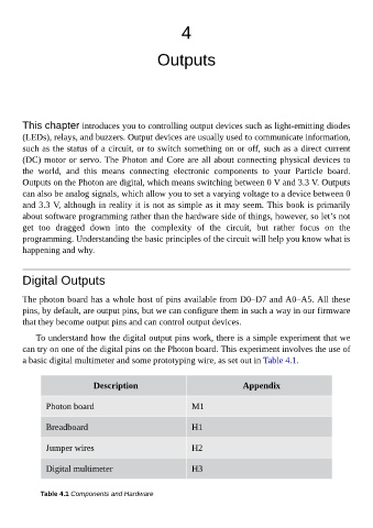
To understand how the digital output pins work, there is a simple experiment that we
can try on one of the digital pins on the Photon board. This experiment involves the use of
a basic digital multimeter and some prototyping wire, as set out in Table 4.1.
Description Appendix
Photon board M1
Breadboard H1
Jumper wires H2
Digital multimeter H3
Table 4.1 Components and Hardware