
Page 75 - Programming the Photon Getting Started With the Internet of Things
P. 75
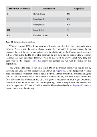
Schematic Reference                       Description                           Appendix


          M1                             Photon board                              M1


                                         Breadboard                                H1


                                         Jumper wires                              H2


          D1                             5-mm LED                                  S1


          R1                             220-ohm resistor                          R1


        Table 4.2 Components and Hardware

             With all types of LEDs, the current only flows in one direction: from the anode to the
        cathode.  As  a  result,  the  anode  should  always  be  connected  to  power  source.  In  our
        instance, this will be the voltage output from the digital pin on the Photon board, which is

        3.3  V.  When  using  LEDs,  it  is  also  common  to  see  them  run  in  series  with  a  resistor.
        Resistors  are  not  polarized;  therefore,  you  do  not  need  to  worry  about  how  they  are
        connected  to  the  circuit.  Table  4.2  shows  the  components  we  will  be  using  for  this
        experiment.

             You will need to connect the LED to pin D0 on the Photon board; you can do this by

        inserting the LED into the breadboard as shown in Figure 4.3. Don’t forget that we also
        need to connect a resistor in series to act as a current limiter, which will prevent damage to
        the LED or the Photon board. The larger the resistor value, the more it will restrict the
        flow of current and the dimmer the LED will glow. Connect the resistor to pin D0 and the

        other end to the anode of the LED (the longest leg). Take a jumper wire and connect the
        cathode leg of the LED to the GND pin on the Photon board (refer to Figures 4.3 and 4.4
        to see how to wire the circuit).