
Page 72 - Programming the Photon Getting Started With the Internet of Things
P. 72
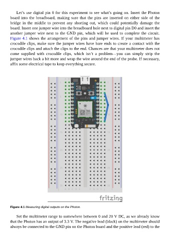
Let’s use digital pin 0 for this experiment to see what’s going on. Insert the Photon
        board  into  the  breadboard,  making  sure  that  the  pins  are  inserted  on  either  side  of  the
        bridge  in  the  middle  to  prevent  any  shorting  out,  which  could  potentially  damage  the

        board. Insert one jumper wire into the breadboard hole next to digital pin D0 and insert the
        another  jumper  wire  next  to  the  GND  pin,  which  will  be  used  to  complete  the  circuit.
        Figure 4.1 shows the arrangement of the pins and jumper wires. If your multimeter has
        crocodile clips, make sure the jumper wires have bare ends to create a contact with the

        crocodile clips and attach the clips to the end. Chances are that your multimeter does not
        come  supplied  with  crocodile  clips,  which  isn’t  a  problem—you  can  simply  strip  the
        jumper wires back a bit more and wrap the wire around the end of the probe. If necessary,
        affix some electrical tape to keep everything secure.


        Figure 4.1 Measuring digital outputs on the Photon.


             Set the multimeter range to somewhere between 0 and 20 V DC, as we already know
        that the Photon has an output of 3.3 V. The negative lead (black) on the multimeter should

        always be connected to the GND pin on the Photon board and the positive lead (red) to the