
Page 80 - Programming the Photon Getting Started With the Internet of Things
P. 80
Pin Number Pin Name Pin Function
1 VSS Ground
2 VDD +5V
3 V0 Contrast adjustment
4 RS Register selection
5 RW Read/write
6 EN Enable
7 D0 Data line 0
8 D1 Data line 1
9 D2 Data line 2
10 D3 Data line 3
11 D4 Data line 4
12 D5 Data line 5
13 D6 Data line 6
14 D7 Data line 7
15 A Backlight anode
16 K Backlight cathode
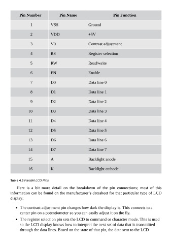
Table 4.3 Parallel LCD Pins
Here is a bit more detail on the breakdown of the pin connections; most of this
information can be found on the manufacturer’s datasheet for that particular type of LCD
display:
The contrast adjustment pin changes how dark the display is. This connects to a
center pin on a potentiometer so you can easily adjust it on the fly.
The register selection pin sets the LCD to command or character mode. This is used
so the LCD display knows how to interpret the next set of data that is transmitted
through the data lines. Based on the state of that pin, the data sent to the LCD