
Page 81 - Programming the Photon Getting Started With the Internet of Things
P. 81
display is either a command or a character.
The RW pin is always connected to the GND pin because we are only ever writing to
the LCD display and not reading the data.
The EN pin is used to tell the LCD display that you are ready to send data.
Data pins 4–7 are used for actually transmitting data, whereas data pins 0–3 are left
unconnected.
Some LCD displays have backlit illumination in various colors. You can connect this
just like you would an LED to the Photon, using the anode and cathode pins with a
resistor in series.
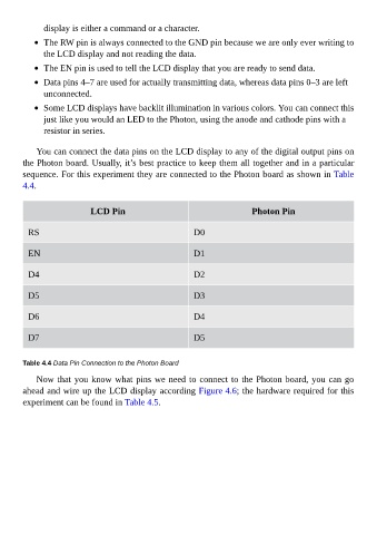
You can connect the data pins on the LCD display to any of the digital output pins on
the Photon board. Usually, it’s best practice to keep them all together and in a particular
sequence. For this experiment they are connected to the Photon board as shown in Table
4.4.
LCD Pin Photon Pin
RS D0
EN D1
D4 D2
D5 D3
D6 D4
D7 D5
Table 4.4 Data Pin Connection to the Photon Board
Now that you know what pins we need to connect to the Photon board, you can go
ahead and wire up the LCD display according Figure 4.6; the hardware required for this
experiment can be found in Table 4.5.