
Page 82 - Programming the Photon Getting Started With the Internet of Things
P. 82
Schematic Reference Description Appendix
M1 Photon board M1
Breadboard H1
Jumper wires H2
H1 16 × 2 LCD display H4
R1 10-K potentiometer R2
Table 4.5 Components and Hardware
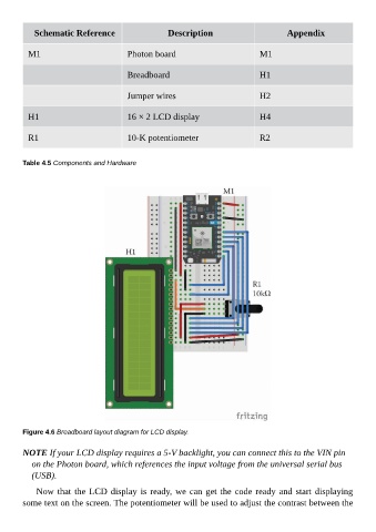
Figure 4.6 Breadboard layout diagram for LCD display.
NOTE If your LCD display requires a 5-V backlight, you can connect this to the VIN pin
on the Photon board, which references the input voltage from the universal serial bus
(USB).
Now that the LCD display is ready, we can get the code ready and start displaying
some text on the screen. The potentiometer will be used to adjust the contrast between the