
Page 88 - Programming the Photon Getting Started With the Internet of Things
P. 88
for(int fadeValue = 0 ; fadeValue <= 255; fadeValue ++) {
// sets the value (range from 0 to 255):
analogWrite(ledPin, fadeValue);
// wait for 30 milliseconds to see the dimming effect
delay(30);
}
// fade out from max to min in increments of 5 points:
for(int fadeValue = 255 ; fadeValue >= 0; fadeValue --) {
// sets the value (range from 0 to 255):
analogWrite(ledPin, fadeValue);
// wait for 30 milliseconds to see the dimming effect
delay(30);
}
}
Run the program and see what happens. You should see the LED change from off to
on, then on to off. This is because of the pattern in the for loop, which repeats itself
indefinitely. In the first for loop i++ is shorthand code for i = i + 1, which always adds a
plus one to the value of i. Similarly i— subtracts 1 from the value; the first loop adds up
the value to 255, and the second loop subtracts it back down to 0.
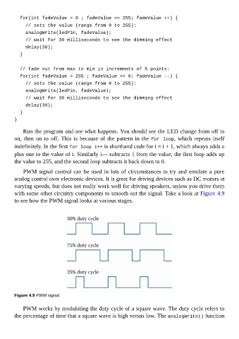
PWM signal control can be used in lots of circumstances to try and emulate a pure
analog control over electronic devices. It is great for driving devices such as DC motors at
varying speeds, but does not really work well for driving speakers, unless you drive them
with some other circuitry components to smooth out the signal. Take a look at Figure 4.9
to see how the PWM signal looks at various stages.
Figure 4.9 PWM signal.
PWM works by modulating the duty cycle of a square wave. The duty cycle refers to
the percentage of time that a square wave is high versus low. The analogWrite() function