
Page 91 - Programming the Raspberry Pi Getting Started with Python
P. 91
9
Interfacing Hardware
The Raspberry Pi has a double row of pins on one side of it. These pins are called the GPIO
connector (General Purpose Input/Output) and allow you to connect electronic hardware to the Pi as an
alternative to using the USB port.
The maker and education communities have already started producing expansion and prototyping
boards you can attach to your Pi so you can add your own electronics. This includes everything from
simple temperature sensors to relays. You can even convert your Raspberry Pi into a controller for a
robot.
In this chapter, we explore the various ways of connecting the Pi to electronic devices using the
GPIO. We’ll use some of the first products that have become available for this purpose. Because this
is a fast-moving field, it is fairly certain that new products will have come on the market since this
chapter was written; therefore, check the Internet to see what is current. I have tried to choose a
representative set of different approaches to interfacing hardware. Therefore, even if the exact same
versions are not available, you will at least get a flavor of what is out there and how to use it.
Products to help you attach electronics to your Pi can be categorized as either expansion boards or
prototyping tools. Before we look at each of these items, we will look at exactly what the GPIO
connector provides us.
GPIO Pin Connections
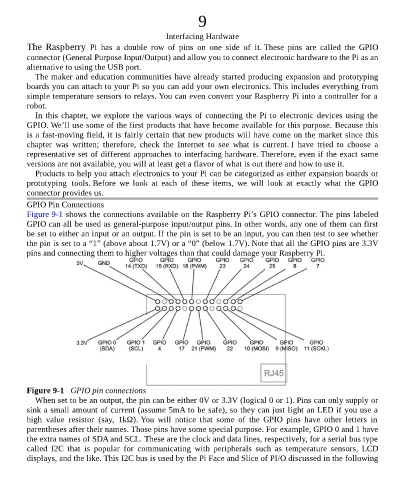
Figure 9-1 shows the connections available on the Raspberry Pi’s GPIO connector. The pins labeled
GPIO can all be used as general-purpose input/output pins. In other words, any one of them can first
be set to either an input or an output. If the pin is set to be an input, you can then test to see whether
the pin is set to a “1” (above about 1.7V) or a “0” (below 1.7V). Note that all the GPIO pins are 3.3V
pins and connecting them to higher voltages than that could damage your Raspberry Pi.
Figure 9-1 GPIO pin connections
When set to be an output, the pin can be either 0V or 3.3V (logical 0 or 1). Pins can only supply or
sink a small amount of current (assume 5mA to be safe), so they can just light an LED if you use a
high value resistor (say, 1kΩ). You will notice that some of the GPIO pins have other letters in
parentheses after their names. Those pins have some special purpose. For example, GPIO 0 and 1 have
the extra names of SDA and SCL. These are the clock and data lines, respectively, for a serial bus type
called I2C that is popular for communicating with peripherals such as temperature sensors, LCD
displays, and the like. This I2C bus is used by the Pi Face and Slice of PI/O discussed in the following