
Page 92 - Programming the Raspberry Pi Getting Started with Python
P. 92
sections.
GPIO pins 14 and 15 also double as the Rx and Tx (Receive and Transmit) pins for the Raspberry
Pi’s serial port. Yet another type of serial communication is possible through GPIO 9 to 11 (MISO,
MOSI, and SCLK). This type of serial interface is called SPI.
Finally, GPIO 18 and GPIO 21 are labeled PWM, meaning that they are capable of pulse width
modulation. This technique allows you to control the power to motors, LEDs etc. by varying the width
of pulses generated at a constant rate.
Direct Connection to GPIO Pins
With care, it is possible to attach simple electronics such as LEDs directly to the GPIO pins; however,
only do this if you know what you are doing because you could easily damage your Raspberry Pi. In
fact, this is more or less what we will be doing in the later section “Prototyping Boards.”
Expansion Boards
Expansion boards usually have screw terminals and a certain amount of electronics already built in.
This makes them very suitable for educational use as well as for those who do not want to get deeply
involved in the electronics side of things. In general, no soldering needs to be done with these kind of
boards. They will usually “buffer” all the connections to the Raspberry Pi, which means the Raspberry
Pi is protected from anything untoward occurring on the expansion board. For example, a short circuit
across an output might damage the expansion board, but no harm will befall your precious Pi.
The sections that follow detail some of the more popular boards, explain their features, and detail
how you might go about using them. One such board (the RaspiRobotBoard) will be used to create a
simple robot in Chapter 11.
Pi Face
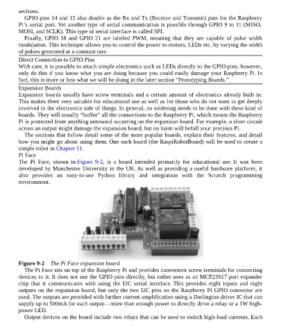
The Pi Face, shown in Figure 9-2, is a board intended primarily for educational use. It was been
developed by Manchester University in the UK. As well as providing a useful hardware platform, it
also provides an easy-to-use Python library and integration with the Scratch programming
environment.
Figure 9-2 The Pi Face expansion board
The Pi Face sits on top of the Raspberry Pi and provides convenient screw terminals for connecting
devices to it. It does not use the GPIO pins directly, but rather uses as an MCP23S17 port expander
chip that it communicates with using the I2C serial interface. This provides eight inputs and eight
outputs on the expansion board, but only the two I2C pins on the Raspberry Pi GPIO connector are
used. The outputs are provided with further current amplification using a Darlington driver IC that can
supply up to 500mA for each output—more than enough power to directly drive a relay or a 1W high-
power LED.
Output devices on the board include two relays that can be used to switch high-load currents. Each