
Page 217 - Radar Technology Encyclopedia
P. 217
207 generator, sweep GUIDANCE, radar
started by the synchronizing pulse of the radar station, a cir- distortion characteristics and complete repeatability of wave-
cuit for shaping pulses of frequency f cos f, f sin f, a pulse forms, very important in pulse-compression radars. SAL
counter, and digital-to-analog converters. The latter shape the Ref.: Skolnik (1990), p. 10.7.
signal modulated by sinf and cosf arriving at the perpendicu-
Waveform To filter
lar coils of the cathode-ray tube. IAM Counter PROM DAC
triggering and upconverter
Ref.: Puckle (1944); Druzhinin (1967), p. 249; Finkel’shteyn (1983), p. 524.
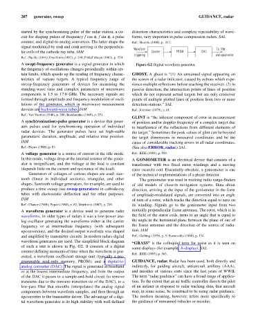
A swept-frequency generator is a signal generator in which Figure G2 Digital waveform generator.
the frequency of oscillations changes periodically within cer-
tain limits, which speeds up the reading of frequency charac- GHOST. A ghost is “(1) An unwanted signal appearing on
teristics of various targets. A typical frequency range of the screen of a radar indicator, caused by echoes which expe-
sweep-frequency generators of devices for measuring the rience multiple reflections before reaching the receiver. (2) In
standing-wave ratio and complex parameters of microwave passive detection, the intersection points of lines of position
components is 1.5 to 17.0 GHz. The necessary signals are which do not represent actual targets but are only crossover
formed through amplitude and frequency modulation of oscil- points of multiple plotted lines of position from two or more
lations of the generator, which in microwave measurement detection stations.” SAL
devices are backward-wave tubes. IAM Ref.: Johnston (1979), p. 61.
Ref.: Van Voorhis (1948), p. 286; Bondarenko (1969), p. 251.
GLINT is “the inherent component of error in measurement
A synch(ronization)-pulse generator is a device that gener- of position and/or doppler frequency of a complex target due
ates pulses used for synchronizing operation of individual to interference of the reflections from different elements of
radar devices. The generator pulses have set high-stable the target.” Sometimes the peak values of glint can lie beyond
parameters: duration, amplitude, and relative time position. the target dimensions in measured coordinates and be the
IAM cause of considerable tracking errors in all radar coordinates.
Ref.: Popov (1980), p. 83. (See also ERROR, radar.) SAL
A voltage generator is a source of current in the idle mode. Ref.: IEEE (1993), p. 559.
In this mode, voltage drop at the internal resistor of the gener- A GONIOMETER is an electrical device that consists of a
ator is insignificant, and the voltage at the load is constant transformer with two fixed stator windings and a moving
(depends little on the current and resistance of the load). rotor (search) coil. Essentially obsolete, a goniometer is one
Generators of voltages of various shapes are used: saw- of the technical implementations of a phase detector.
tooth (linear in individual sections), triangular, and other The goniometer was used in tracking radio range-finders
shapes. Sawtooth voltage generators, for example, are used to of old models of close-in navigation systems. Data about
produce a time sweep (see sweep generators) in cathode-ray direction, arriving at the input of the goniometer in the form
tubes with electrostatic deflection and for other purposes. of amplitude-modulated signals, are converted into an angle
IAM of turn of a rotor, which tracks the direction equal to zero on
Ref.: Chance (1949); Popov (1980), p. 82; Druzhinin (1967), p. 249. its winding. Signals go to the goniometer input from two
A waveform generator is a device used to generate radar mutually perpendicular frame antennas. The rotor, which is in
waveforms. In older types of radars it was a low-power ana- the field of the stator coils, turns to an angle that is equal to
log oscillator generating the waveforms either at the carrier the angle in the horizontal plane between the plane of one of
frequency or at intermediate frequency (with subsequent the frame antennas and the direction of the source of radia-
upconversion), and the desired output waveform was shaped tion. IAM
and amplified by transmitter circuits. In modern radars digital Ref.: Gething (1978), p. 5; Sosnovskiy (1990), p. 134.
waveform generators are used. The simplified block diagram
“GRASS” is the colloquial term for noise as it is seen on
of such a unit is shown in Fig. G2. It consists of a digital
some displays (for example, A-display). SAL
counter defining moments of time when the waveform is gen-
Ref.: IEEE (1993), p. 563.
erated, a waveform coefficient storage unit (typically a pro-
grammable read-only memory, PROM), and a digital-to- GUIDANCE, radar. Radar has been used, both directly and
analog converter (DAC). The signal is generated at baseband indirectly, for guiding aircraft, antiaircraft artillery (AAA),
or at the lowest intermediate frequency, and from the output and missiles of various sorts since the last years of WWII.
of the DAC it passes to a sample-and-hold circuit (to remove The term “radar guidance” can have a broad range of applica-
transients due to the nonzero transition tie of the DAC), to a tion. To the extent that an air traffic controller directs the pilot
low-pass filter that smooths (interpolates) the analog signal of an airliner in response to radar tracking data, that aircraft
components between waveform samples, and then through an may, in some sense, be construed to be using radar guidance.
upconverter to the transmitter driver. The advantage of a digi- The modern meaning, however, refers more specifically to
tal waveform generator is its high stability with well-defined the guidance of unmanned vehicles or missiles.