
Page 220 - Radar Technology Encyclopedia
P. 220
height-finder, squinted-beam HOLOGRAM, HOLOGRAPHY, radar 210
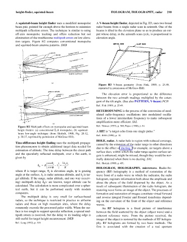
A squinted-beam height finder uses a modified monopulse A V-beam height finder, depicted in Fig. H3, uses two broad
beam pair, pointed far enough above the horizon to minimize radar beams from a single radar scan in azimuth. One of the
multipath reflection errors. The technique is similar to using beams is tilted in the elevation plane so as to produce an out-
off-axis monopulse tracking and offers reduction but not put whose delay, in the azimuth scan cycle, is proportional to
elimination of the troublesome multipath errors on low-eleva- elevation angle.
tion targets. Figure H2 compares conventional monopulse
and squinted-beam antenna patterns. DKB
Figure H3 V-beam geometry (from Fink, 1989, p. 25.49,
reprinted by permission of McGraw-Hill).
The elevation error is proportional to the difference
between the two azimuth readings multiplied by the cotan-
gent of the tilt angle. (See also PATTERN, V-beam).PCH
Ref.: Fink (1989), p. 25.49.
HETERODYNING is the process of the conversion of mod-
ulated radio-frequency oscillations into modulated oscilla-
tions of a lower intermediate frequency to make subsequent
amplification more efficient. SAL
Figure H2 Multipath effects on monopulse and squinted-beam Ref.: Terman (1955), p. 568; Popov (1980), p. 84.
height finders: (a) conventional S,D monopulse, (b) squinted-
A HIT is “a target echo from one single pulse.”
beam low-angle technique (from Skolnik, 1990, Fig. 20.12,
Ref.: IEEE (1990), p. 18.
p. 20.37, reprinted by permission of McGraw-Hill).
HOLE, radar. A radar hole is region with reduced coverage,
Time-difference height finding uses the multipath propaga-
caused by the extension of the radar range in other directions
tion phenomenon to obtain additional target data needed for
due to the effect of ducting. For example, air targets above a
estimation of altitude. The time delay between the direct path
surface duct, within which the radar range against surface tar-
and the specularly reflected multipath, over a flat earth, is
gets is enhanced, might be missed, though they would be nor-
given by
mally detected when there is no ducting. SAL
cos q 2h h Ref.: Skolnik (1980), p. 451.
t
r t
d = R ------------- – 1 » -------------
0 cos y R HOLOGRAM, HOLOGRAPHY, microwave. Radio-fre-
where R is target range, q is elevation angle, y is grazing quency (RF) holography is a method of restoration of the
t
angle at the surface, h is radar antenna altitude, and h is tar- wave front of a radio wave in which the indicator, the radio
t
r
get altitude. If the range, radar altitude, and one-way (receiv- hologram, registers information both about the amplitude and
ing) multipath delay d /c are known, target altitude can be about the phase of the field dispersed by the object. As a
0
calculated. The calculation is more complicated over a spher- result of subsequent illumination of the radio hologram, the
ical earth, but it can be performed easily with modern restoring wave forms an image of the object. The processes of
computers. formation and restoration of images constitute virtual forward
The multipath delay is very small for surface-based and reverse integral Fourier and Fresnel transforms depend-
radars, so the technique is restricted in practice to airborne ing on the curvature of the front of the object and reference
radars and those on high mountain sites, where the delay waves.
commonly exceeds the processed pulse width. When the sur- An RF hologram is a fixed picture of interference
face is too rough to support specular reflection, a spread mul- between the field scattered by the object (object wave) and a
tipath return is received, but the delay to its leading edge is coherent reference wave. From the picture received, the
still useful for target height measurement. DKB image of the object is restored by the methods of RF hologra-
Ref.: Long (1992), p. 349. phy. RF holograms are formed by two basic methods. The
first is associated with the creation of a real aperture