
Page 225 - Radar Technology Encyclopedia
P. 225
215 image correction imaging, range-doppler
The basic methods of image correction are allowance for forms can be used. Three channels are required or 3D
data regarding trajectory deviations when recording the monopulse imaging: a sum channel and two difference chan-
image (control of recording speed and registration delay), sta- nels. SAL
bilization of the antenna in space, and electrical control of the Ref.: Wehner (1987), pp. 341–369; Currie (1989), p. 397.
antenna beam.
Image correction is necessary both in conventional radars
with a conventional antenna, and in radars with a synthesized
aperture, since in the latter case for the above reasons the
dynamic range of output signals is reduced, along with reso-
lution; and with angular oscillations in the radar platform,
also the image contrast. IAM
Ref.: Kondratenkov (1983), p. 113; Curlander (1991), Ch. 8.
Image decoding is the process of detection, discrimination,
and determination of location of various objects, and also
determination of the nature of the terrain and its elements
from their radar image. Detection and discrimination of
objects is based on analysis of the tone, shape, and size of the
radar image of the object, the shape of its shadow, and other
features. The coordinates of objects are determined by vari-
ous methods from the registered coordinates of the radar plat-
form, and the known size of the image with its scale marks,
and also by the methods of topographic survey. The latter
method is based on measurement of object coordinates of rel-
atively known terrain elements in the image, whose coordi- Figure I1 Image created using focused beam antenna (from
Currie, 1989, Fig. 10.16, p. 398).
nates are determined from a topographic map. The method of
reference to a topographic map has great precision, since it is
not associated with the errors of the navigational system of
the radar platform.
The basic problem of automatic decoding is the process-
ing of object discrimination. For this reason, it is usually lim-
ited to automation of certain operations (processing of a large
number of images, search for frames with given objects, large
changes in density, or returns from moving objects, etc.). IAM
Ref.: Kondratenkov (1983), p. 133; Curlander (1991), p. 412.
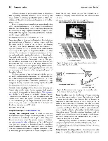
Focused-beam imaging is three-dimensional imaging per-
formed using a radar with a focused antenna. Such imaging Figure I2 Three-dimensional imaging with monopulse radar
can be used, for example, in high-resolution RCS measure- (from Wehner, 1987, Fig. 8.2, p. 343).
ment. In Fig. I1, a 3D image received with a focused Casseg-
Range imaging uses the distribution of target scattering
rainian antenna is shown. In this case, the antenna beam was
sources along one coordinate: range. The basic type of such
raster-scanned across the target at different elevation angles
an image is distribution of amplitudes or RCS of the target in
to develop the image, the range dimension resolution was
range that is sometimes termed a target range profile. To
about 30 cm, and a spot less than 30 cm in diameter was
obtain it, pulse-compression waveforms are used to increase
developed at a range about 75m. SAL
the range resolution. For target dimensions that significantly
Ref.: Currie (1989), p. 396.
exceed the wavelength, the range profile is represented in the
holographic imaging (see HOLOGRAM). form of signal amplitudes reflected by individual illuminated
points of the target. When ultrawideband signals are used, it is
Imaging, with monopulse radar, is based on wideband
possible to obtain an image in the form of a profiled target
monopulse radar processing that makes it possible to measure
function that characterizes the distribution of area of the tar-
the position of an isolated point target in two orthogonal
get section along the radar beam.
dimensions of cross-range. The general process of the imag-
The target range profile is widely used for recognition of
ing with monopulse radar is illustrated in Fig. I2. Differential
aerospace targets (aircraft, missiles, and spacecraft). IAM
error signals are produced in the azimuth and elevation chan-
Ref.: Nebabin (1984), p. 103, (1995), p. 110; Wehner (1987), p. 148; Astanin
nels of a monopulse radar, and orthogonal cross-range dimen- (1989), p. 173.
sions are obtained from these error signals. To resolve targets
Range-doppler imaging produces a two-dimensional radar
in slant range, pulse-compression or stepped-frequency wave-
image of a target that characterizes the distribution of ampli-