
Page 230 - Radar Technology Encyclopedia
P. 230
integrator, analog integration, coherent [predetection] 220
imately 1.6 dB lower than that of the n-pulse video integrator.
(see integration gain). The probability P of detection or false
alarm at the output of a binary integrator can be found as a
function of the corresponding probability p at its input as
n
n! j n – j
Pm n ¤( ) = å --------------------- p 1 – p )
(
(
j! n – ) !
j
j = m
Several common cases are:
P(1/1) = p
2
P(1/2) = p + 2p(1 - p)
2
3
P(2/3) = p + 3p (1 - p)
4
2
3
P(2/4) = p + 4p (1 - p) + 6p (1 - p)
The general block diagram of the binary integrator is
shown in Fig. I5. If the binary counter is periodically decre-
mented to maintain a low false-alarm probability on a contin-
uous stream of input signals, the integrator is known as a
Figure I3 Delay-line based integrator: (a) block diagram, (b)
moving-window (or continuous) binary integrator. Otherwise,
frequency response.
it is a batch integrator, in which the counter is set to zero after
Depending on the type of delay line, analog integrators each group of n pulses.
are divided into dynamic and static integrators. The latter are Although the binary integrator introduces an additional
often termed synchronous integrators. In dynamic integra- loss relative to the ideal noncoherent integrator, it is much
tors, typically ultrasonic delay lines or surface-acoustic-wave less sensitive to the effects of large, random interference
delay lines are employed. In static integrators, the delay of the pulses because the energy in a single pulse contributes no
pulses is implemented through its recording in magnetic tape, more than a single “one” in the binary counter, rather than its
disk, or cathode-ray tube. The reading is done in the desired large voltage in the linear integrator.
moment of time. These integrators have poor performance.
First Second
The general disadvantage of one-cycle integrators is a com- threshold threshold Target
pulse
Binary
Count
Radar
paratively small improvement of the signal-to-noise ratio. It receiver Video Threshold Quantizer Range gate counter sampler
detector
No. 1
can be increased by using a two-cycle integrator (Fig. I4) that
can have a signal-to-noise ratio improvement about twice that
Range gate Binary Count
of the one-cycle integrator. AIL No. 2 counter sampler
Ref.: Skolnik (1970), p. 17.27; Finkel’shteyn (1983), pp. 265–280; Lezin
(1969), pp. 256–276. Range gate Binary Count
No. 3 counter sampler
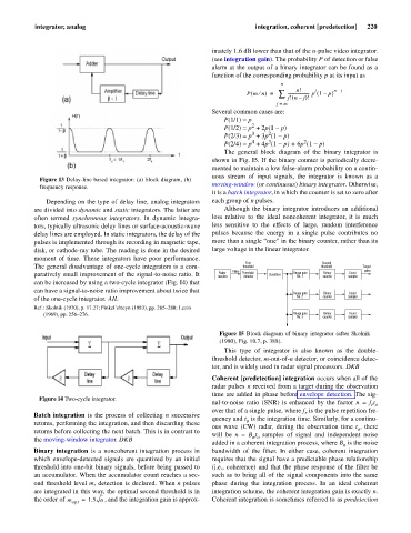
Figure I5 Block diagram of binary integrator (after Skolnik
(1980), Fig. 10.7, p. 388).
This type of integrator is also known as the double-
threshold detector, m-out-of-n detector, or coincidence detec-
tor, and is widely used in radar signal processors. DKB
Coherent [predetection] integration occurs when all of the
radar pulses n received from a target during the observation
time are added in phase before envelope detection. The sig-
Figure I4 Two-cycle integrator.
nal-to-noise ratio (SNR) is enhanced by the factor n = f t
r o
over that of a single pulse, where f is the pulse repetition fre-
r
Batch integration is the process of collecting n successive
quency and t is the integration time. Similarly, for a continu-
o
returns, performing the integration, and then discarding these
ous wave (CW) radar, during the observation time t , there
o
returns before collecting the next batch. This is in contrast to
will be n = B t samples of signal and independent noise
n o
the moving-window integrator. DKB
added in a coherent integration process, where B is the noise
n
Binary integration is a noncoherent integration process in bandwidth of the filter. In either case, coherent integration
which envelope-detected signals are quantized by an initial requires that the signal have a predictable phase relationship
threshold into one-bit binary signals, before being passed to (i.e., coherence) and that the phase response of the filter be
an accumulator. When the accumulator count reaches a sec- such as to bring all of the signal components into the same
ond threshold level m, detection is declared. When n pulses phase during the integration process. In an ideal coherent
are integrated in this way, the optimal second threshold is in integration scheme, the coherent integration gain is exactly n.
the order of m = 1.5 n , and the integration gain is approx- Coherent integration is sometimes referred to as predetection
opt