
Page 235 - Radar Technology Encyclopedia
P. 235
225 IONOSPHERE jamming, active
signals of multifrequency radio transmitters installed aboard A waveguide iris is a matching iris with a thin metal partition
special satellites serve as passive radar signal sources. When placed in the waveguide circuit to cover part of its cross-sec-
active radar methods are used to determine the characteristics tion. In a rectangular waveguide, the most common are the
of the ionosphere, artificial ionized formations of a type of symmetrical inductive, symmetrical capacitive, and resonant
barium clouds are used widely, along with direct probing of irises. The first two are used as matching devices (see IRIS,
the researched regions. An ionospheric storm mainly impacts matching). For precise calculations of parameters of irises,
operation of decimetric waveband OTH radars and a portion special graphs or computer programs are used. IAM
of the operation of metric band radars, as well as communica- Ref.: Montgomery (1947), Ch. 6; Sazonov (1988), p. 65.
tions equipment operating at wavelengths greater than 10m.
AIL
Ref.: Blake (1982); Kolosov (1984), p. 112; Dolukhanov (1972), pp. 184–
235. J
IRIS, matching. A matching iris is a waveguide capacitive or
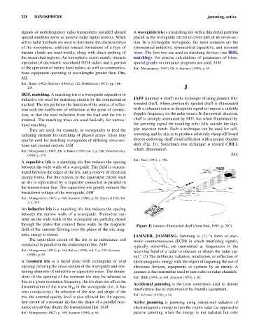
inductive iris used for matching circuits by the compensation JAFF (jammer + chaff) is the technique of using jammer-illu-
method. The iris performs the function of the source of reflec- minated chaff, where previously ejected chaff is illuminated
tion with the coefficient of reflection at the point of connec- with a coherent noise or deception signal to impose a suitable
tion, so that the total reflection from the load and the iris is doppler frequency on the radar return. In the normal situation,
minimal. The matching irises are used basically for narrow- chaff is strongly attenuated by MTI, but when illuminated by
band matching. the jamming signal the resulting echo falls outside the dop-
They are used, for example, in waveguides to feed the pler rejection notch. Such a technique can be used for self-
radiating element for matching of phased arrays. Irises may screening and its aim is to produce relatively cheap off-board
also be used for matching waveguides of differing cross-sec- decoys endowing chaff cloud reflection with a proper doppler
tions and coaxial circuits. IAM shift (Fig. J1). Sometimes this technique is termed CHILL
(chaff, illuminated).
Ref.: Montgomery (1947), Ch. 6; Rakov (1970) vol. 2, p. 248; Voskresenskiy
(1981) p. 219. SAL
Ref.: Neri (1991), p. 396.
A capacitive iris is a matching iris that reduces the spacing
between the wide walls of a waveguide. The field is concen-
trated between the edges of the iris, and a reserve of electrical
energy forms. For this reason, in the equivalent circuit such
an iris is represented by a capacitor connected in parallel to
the transmission line. The capacitive iris greatly reduces the
breakdown voltage of the waveguide. IAM
Ref.: Montgomery (1947), p. 166; Sazonov (1988), p. 65; Rakov (1970), Vol
2, p. 249.
An inductive iris is a matching iris that reduces the spacing
between the narrow walls of a waveguide. Transverse cur-
rents on the wide walls of the waveguide are partially closed
through the plates that connect these walls. In the magnetic Figure J1 Jammer-illuminated chaff (from Neri, 1991, p. 397).
field of the currents flowing over the plates of the iris, mag-
netic energy is stored. JAMMER, JAMMING. Jamming is (1) “a form of elec-
The equivalent circuit of the iris is an inductance coil tronic countermeasures (ECM) in which interfering signals,
connected in parallel to the transmission line. IAM typically noise-like, are transmitted at frequencies in the
Ref.: Montgomery (1947), p. 164; Rakov (1970), vol. 2, p. 248; Sazonov receiving band of a radar to obscure or distort the radar sig-
(1988), p. 65.
nal.” (2) The deliberate radiation, reradiation, or reflection of
A resonant iris is a metal plate with rectangular or oval electromagnetic energy with the object of impairing the use of
opening covering the cross-section of the waveguide and con- electronic devices, equipment, or systems by an enemy. A
taining elements of inductive or capacitive irises. The dimen- jammer is the transmitter used to jam radio or radar channels.
sions of the opening of the resonant iris may be selected so Ref.: IEEE (1993), p. 691; Johnston (1979), p. 62.
that at a given resonance frequency, the iris does not affect the
Accidental jamming is the term sometimes used to denote
dissemination of the wave H in the waveguide (i.e., it has interference due to transmission by friendly equipment.
10
zero conductivity). In selection of the size and shape of the
Ref.: Johnston (1979), p. 56.
iris, the external quality level is also allowed for. An equiva-
lent circuit of a resonant iris has the shape of a parallel reso- Active jamming is jamming using intentional radiation of
nance circuit that shunts the transmission line. IAM electromagnetic energy to jam the victim radar (as opposed to
Ref.: Montgomery (1947), p. 169; Sazonov (1988), p. 66. passive jamming when the energy is not radiated but only