
Page 231 - Radar Technology Encyclopedia
P. 231
221 integration, coherent [predetection] integrator, multichannel
integration, in that it occurs in the radar receiver before the order of declining integration efficiency and declining com-
second (envelope) detector. PCH plexity of implementation, in which the information from n
Ref.: Barton (1991), pp. 4–11. pulses or samples may be processed to improve the radar
detection performance: (1) coherent integration, (2) nonco-
Continuous integration is an n-pulse integration process in
herent (or video) integration, (3) binary integration, and (4)
which a new integrated value is formed after reception of
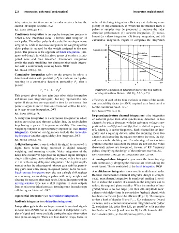
cumulative integration. Figure I6 compares the integration
each pulse. The oldest pulse is discarded in moving-window
integration, while in recursive integrators the weighting of the
older pulses is reduced by the weight assigned to the new
pulse. The process is the opposite of batch integration (inte-
grate-and-dump), in which a given group of n pulses is inte-
grated once and then discarded. Continuous integration
avoids the angle straddling loss characterizing batch integra-
tion with a continuously scanning beam. DKB
Ref.: Skolnik (1980), p. 390.
Cumulative integration refers to the process in which a
detection decision with probability P is made on each pulse,
1
resulting in a cumulative detection probability P after n
c
pulses:
n
P = 1 – ( 1 – P ) Figure I6 Comparison of detectability factors for four methods
c 1
of integration (from Barton, 1988, Fig. 2.3.3, p. 75).
This process gives far less gain than other video integration
techniques (see integration gain), but may represent the only efficiency of each of the four methods in terms of the result-
option if the pulses are separated in time by an interval that ant detectability factor (or SNR) required as a function of n
permits targets to move from one resolution cell to the next, for the conditions noted. PCH
as in scan-to-scan integration. DKB
Ref.: Barton (1991), pp. 4–14.
Ref.: Barton (1988), p. 74.
In-phase/quadrature channel integration is the integration
A delay-line integrator is a continuous integrator in which of coherent pulse train after synchronous detection in two
pulses are recirculated through a delay line, the recirculation channels by phase detectors with the reference voltages pro-
loop having a gain < 1 to preserve stability. The resulting portional to cos2pf t and sin2pf t; that is, shifted in phase by
0
0
weighting function is approximately exponential (see analog p/2, re f is carrier frequency. Each channel has an inte-
wh
e
0
integrator). Common configurations include the recirculat- grator and a squaring device. After the summing these two
ing integrator and the tapped-delay-line integrator. DKB channel and extracting the square root from the sum, the sig-
Ref.: Skolnik (1980), p. 390. nal passes to thresholding unit. The advantage of such an inte-
A digital integrator is one in which the signal is converted to gration is that the data about the phase are not lost, but video
digital form before being processed in digital memory, (baseband) pulses are integrated, instead of RF frequency
weighting, and summing circuits. Video integrators of the pulses, simplifying the design of the optimum receiver. AIL
delay-line (recursive) type pass the digitized signal through a Ref.: Finkel’shteyn (1983), pp. 237–239; Schleher (1991), p. 608.
single shift register, recirculating the output with a loop gain A moving-window integrator processes the incoming sig-
< 1 as with analog delay-line integrators. The digital imple- nals continuously, dropping the oldest return when adding the
mentation has the advantage of inherent gain stability, permit- most recent. This is contrasted to the batch integrator. DKB
ting gains near unity (many integrated pulses) to be realized.
A multichannel integrator is one used in multichannel radar.
Batch-process integrators may also use a single shift register
Because multichannel coherent integrator design is compli-
as a memory, accumulating n pulses with unity weights and
cated, noncoherent integration is employed, making it possi-
clearing the register after each batch. Digital integrators of the
ble to reduce the number of channels in the integrator and to
moving-window type use n shift registers to store outputs
reduce the required phase stability. When the number of inte-
from n pulse repetition intervals, forming sums in each range
grated pulses is not too large (less than 20), amplitude recir-
cell during each interval. DKB
culators with delay lines in the positive feedback circuit with
exponential integrator (see recirculator integrator). feedback coefficient b can be efficient (Fig. I7). This integra-
tor has a bank of doppler filters (F .... F ), n detectors (D) and
1
n
feedback integrator (see delay-line integrator).
switches, and a common noncoherent integration unit (adder
Integration gain is the net improvement in received signal- S, modulator M, delay line LN, an amplifier with positive
to-noise ratio (SNR) due to the addition of independent sam- feedback coefficient b, and detector D) for all channels. AIL
ples of signal and noise available during the radar observation Ref.: Lukoshkin (1983), pp. 284–287; Nitzberg (1992), p. 240.
time (time-on-target). There are four distinct ways, listed in