
Page 232 - Radar Technology Encyclopedia
P. 232
integration, multichannel integration time 222
Figure I7 Multichannel recirculating integrator with time mul-
tiplexing of channels.
Noncoherent [video, or postdetection] integration occurs
when n signal samples or pulses are added after passing
through an envelope detector which removes any phase rela-
Figure I9 Integration loss vs. number of pulses integrated
tionships. The integrated SNR is increased by a factor
after envelope detection (from Barton 1988, Fig. 2.3.2, p. 72).
approaching n, but decreased by a detector loss due to a loss
in information for target detection purposes. As the signal
input to the envelope detector decreases, the small signal sup-
pression loss increases as shown in Fig. I8, and further video Output
Adder
integration cannot restore the SNR represented by the total
signal energy ratio. As a result, there is a requirement for
more energy per pulse, which can be considered as integra-
tion loss, which is the ratio of total signal energy required of
Amplifier
the n-pulse train to that which would have been required if a Delay line
b < 1
single pulse had been transmitted and processed, or if a
matched filter for the n-pulse train had been used.
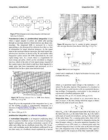
Figure I10 Recirculator integrator.
control unit is employed. A digital recirculator in every cycle
evaluates the sum:,
¥
j
å b y j
j = 0
where y is quantized input voltage at the moments t - jT,
j
where T is the delay interval. The response of a circulator to
the unity pulse is a grid function with an exponential decreas-
ing envelope. Consequently, a recirculator is also termed an
exponential or feedback integrator. IAM
Ref.: Dulevich (1978), pp. 157, 171; Skolnik (1990), pp. 8.5–8.8.
Figure I8 Envelope detector loss vs. SNR (from Barton,
Integration time, also referred to as observation time or
1988, Fig. 2.2.4, p. 64).
time-on-target, is the time during which the target is illumi-
nated by the radar on each scan, that is
Figure I9 gives the magnitude of this integration loss L ver-
i
sus the number of pulse n, noncoherently integrated, as a q 3az t y b
s
function of the detectability factor D (1) for a steady target. t = ---------- = ----------
o
y
w
0
s
s
DKB
where q is the 3-dB azimuth beamwidth of the radar, w is
Ref.: Barton (1988), pp. 69–76. 3 az s
the radar scan rate, t is the radar frame time, y is the radar’s
s
s
predetection integration (see coherent integration). solid angle of search (in steradians), and y is the solid angle
b
of the radar beam. For a scanning pulse radar, there will be
A recirculator integrator is an integrator employing delay
n= t f pulses or samples available for integration during the
units in a positive feedback circuit. It can be done of analog or o r
time-on-target, where f is the pulse repetition frequency. For
digital configuration. An analog recirculator consists of an r
a continuous-wave (CW) radar, or a coherent pulse radar, the
adder and a delay line in a feedback circuit (Fig. I10). To pre-
coherent integration time is not the same as the time-on-target
vent a self-oscillation mode, the feedback coefficient b is set
but is the integration time of the predetection filter, approxi-
less then unity, or a feedback circuit regulated by a special
mately equal to the reciprocal of the filter bandwidth. Subse-