
Page 239 - Radiochemistry and nuclear chemistry
P. 239
Detection and Measurement Techniques 223
8.7. Electronics for pulse counting
A wide variety of counting systems has been developed for various purposes. Equipment
is often built as NIM (Nuclear Instrument Module standard) or CAMAC (Computer
Automated Measurement And Control standard) modules, which fit into standard bins (or
crates) containing power supplies and some inter-module connections. Cable connectors are
also largely standardized. This facilitates combinations of bias supplies, amplifiers,
discriminators, SCAs, ADCs, counters, and other circuitry to fit any need as well as their
connection to computers. Some non-standard units, e.g. portable instruments, have their
own power supply, main amplifier, counter or rate-meter, etc.
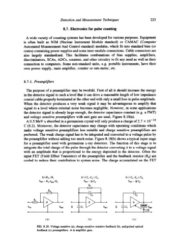
8.7.1. Preamplifiers
The purpose of a preamplifier may be twofold. First of all it should increase the energy
in the detector signal to such a level that it can drive a reasonable length of low impedance
coaxial cable properly terminated at the other end with only a small loss in pulse amplitude.
When the detector produces a very weak signal it may be advantageous to amplify that
signal to a level where external noise becomes negligible. However, in some applications
the detector signal is already large enough, the detector capacitance constant (e.g. a PMT)
and voltage sensitive preamplifiers with unit gain are used, Figure 8.18(a).
A 0.5 MeV 'y absorbed in a germanium crystal will only produce a charge of 2.7 • 10-14
C (8.2). Moreover, the detector capacitance may change with operating conditions which
make voltage sensitive preamplifiers less suitable and charge sensitive preamplifiers are
preferred. The weak charge signal has to be integrated and converted to a voltage pulse by
the preamplifier without adding too much noise. Figure 8.18(b) shows a typical input stage
for a preamplifier used with germanium "y-ray detectors. The function of this stage is to
integrate the total charge of the pulse through the detector converting it to a voltage signal
with an amplitude that is proportional to the energy deposited in the detector. Often the
input FET (Field Effect Transistor) of the preamplifier and the feedback resistor (Rf) are
cooled to reduce their contribution to system noise. The charge accumulated on the FET
A>>R2 IR~ A>>(C~ tCr )/Cr A>>(C~ ,C r J lC r
Vout =-R ~ VoutlR, Vou, = -O/Cl= Vou, = "OlCf
Rr
t ilo, Iic,
RI
=- -- c
V,n Vout 0 Vou, 0
(al (b) (c)
FIG. 8.18. Voltage sensitive (a), charge sensitive resistive feedback Co), and pulsed optical
feedback (c) preamplifiers. A is amplifier gain.