
Page 105 - Reciprocating Compressors Operation Maintenance
P. 105
92. Reciprocating Compressors: Operation and Maintenance
diagrams are plan views with the exception of the fourth arrangement
with cylinders at 90°, an elevation view.
DISTURBING FORCES
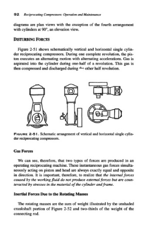
Figure 2-51 shows schematically vertical and horizontal single cylin-
der reciprocating compressors. During one complete revolution, the pis-
ton executes an alternating motion with alternating accelerations. Gas is
aspirated into the cylinder during one-half of a revolution. This gas is
K
then compressed and discharged during * <? other half revolution.
FIGURE 2-51. Schematic arrangement of vertical and horizontal single cylin-
der reciprocating compressors.
Gas Forces
We can see, therefore, that two types of forces are produced in an
operating reciprocating machine. These instantaneous gas forces simulta-
neously acting on piston and head are always exactly equal and opposite
in direction. It is important, therefore, to realize that the internal forces
caused by the working fluid do not produce external forces but are coun-
teracted by stresses in the material of the cylinder and frame.
The rotating masses are the sum of weight illustrated by the unshaded
crankshaft portion of Figure 2-52 and two-thirds of the weight of the
connecting rod.