
Page 104 - Reciprocating Compressors Operation Maintenance
P. 104
Design and Materials for Reciprocating Compressor Components & 1
Force« Couptes
Crank Arrangements
Primary Secondary Stcondan
Single crank ea F' without
counter wts.
0.5 F' without F" None None
counter wts.
F'D without
Two cranks at 1 80° a Zero 2F" counter wts. None
Ml r"i
loP F'D with
In line cylinders JT.!!— 2
• counter wts.
Opposed cylinders rjg^_<->--33 Zero Zero NIL NIL
Two cranks at 90" r-j Q 1. 14 F' without 0.707 F' without
counter wts. counter wts. F'D
5.707 F'wtthoul Zero 0.354 F'O with
IX -TLJ— xMinter wts. counter wts.
Two cylinders on one crank F' without
counter wts. 1.14F"
Zero with NIL NIL
Cylinders at 90° TT counter wts.
Two cylinders on one crank 2 F' without
counter wts.
F'with Zero None NIL
Opposed cylinders r counter wts.
Three cranks at 120° a 3.48 F'D without
T a en counter wts
lefi* T Zero Zero 3.48 F"D
1
JT-.1— L.
**% -Jt-tlnlr- 1.73 F'D wild
counter wts.
Four cylinders fH Fjfl
Zero 4F" Zero Zero
Cranks at 180° I -^^TWi 1.41 F"D without
counter wts.
Cranks at 90° *$•« " | ^ '"""" " Zero Zero 0.707 F-O with 4.0 F"D
counter wts.
A-te-tf- Zero Zero Zero Zero
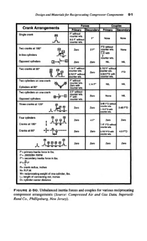
F'= primary inertia force in Ibs.
F'= .0000284 RN'W
F"= secondary inertia force in Ibs.
R= crank radius, inches
N= R.P.M.
We reciprocating weight of one cylinder, Ibs.
L= length of connecting rod, Inches
D= cylinder center distance
FIGURE 2-SO. Unbalanced inertia forces and couples for various reciprocating
compressor arrangements (Source: Compressed Air and Gas Data, Ingersoll-
Rand Co., Phillipsburg, New Jersey).