
Page 101 - Reciprocating Compressors Operation Maintenance
P. 101
88 Reciprocating Compressors: Operation and Maintenance
FIGURE 2-46. Typical crosshead arrangement illustrating load reversal at pin.
(Source: Dresser-Rand, Painted Post, New York).
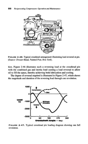
tion. Figure 2-46 illustrates such a reversing load at the crosshead pin
with the combined gas and inertia load causing a load reversal to allow
oil to fill the space, thereby achieving both lubrication and cooling.
The degree of reversal required is illustrated in Figure 2-47, which shows
the magnitude and duration of the reversing load through one revolution.
1000 r
Load
t ) -1000
-2000 -
-3000
0 90 100 270 360
Crankshaft Angle — loegj
FIGURE 2-47. Typical crosshead pin loading diagram showing one full
revolution.