
Page 99 - Reciprocating Compressors Operation Maintenance
P. 99
80 Reciprocating Compressors: Operation and Maintenance
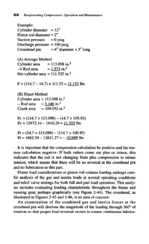
Example:
Cylinder diameter =12"
Piston rod diameter = 2"
Suction pressure = 0 psig
Discharge pressure =100 psig
Crosshead pin = 4" diameter x 5" long
(A) Average Method
2
Cylinder area = 113.098 in.
-M Rod area = 1.573 in. 2
Net cylinder area = 111.525 in. 2
F = (114.7 - 14.7) x 111.53 =ULmibs
(B) Exact Method
Cylinder area = 113.098 in. 2
- Rod area = 3.146 in. 2
2
Crank area = 109.952 in.
Fc = (114.7 x 113.098) - (14.7 x 109.95)
Fc = 12972.34 - 1616.29 = 11.355 Ibs
Ft = (14.7 x 113.098) - (114.7 x 109.95)
Ft= 1662.54-12611.27 = -lM4°Jbs
It is important that the compression calculation be positive and the ten-
sion calculation negative. If both values come out plus or minus, this
indicates that the rod is not changing from plus compression to minus
tension, which means that there will be no reversal at the crosshead pin
and no lubrication to this part.
Frame load considerations or piston rod column loading undergo care-
ful analysis of the gas and inertia loads at normal operating conditions
and relief valve settings for both full and part load operation. This analy-
sis includes evaluating loading characteristic throughout the frame and
running gear, perhaps graphically (see Figure 2-44). The crosshead, as
illustrated in Figures 2-45 and 2-46, is an area of concern.
An examination of the combined gas and inertia forces at the
crosshead pin will disclose the magnitude of the loading through 360° of
rotation so that proper load reversal occurs to ensure continuous lubrica-