
Page 151 - Reciprocating Compressors Operation Maintenance
P. 151
Operation and Maintenance of Reciprocating Compressors 1 37
suction valves, the pressure has to be reversed. These factors explain why
a pressure differential is necessary inside the cylinder versus outside the
cylinder to lift the valve plate off the seat. The difference in area of a seal-
ing element is normally 15 percent to sometimes as high as 30 percent
between exposure underneath, seat side, and exposure on top, guard side.
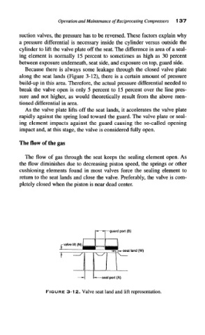
Because there is always some leakage through the closed valve plate
along the seat lands (Figure 3-12), there is a certain amount of pressure
build-up in this area. Therefore, the actual pressure differential needed to
break the valve open is only 5 percent to 15 percent over the line pres-
sure and not higher, as would theoretically result from the above men-
tioned differential in area.
As the valve plate lifts off the seat lands, it accelerates the valve plate
rapidly against the spring load toward the guard. The valve plate or seal-
ing element impacts against the guard causing the so-called opening
impact and, at this stage, the valve is considered fully open.
The flow of the gas
The flow of gas through the seat keeps the sealing element open. As
the flow diminishes due to decreasing piston speed, the springs or other
cushioning elements found in most valves force the sealing element to
return to the seat lands and close the valve. Preferably, the valve is com-
pletely closed when the piston is near dead center.
guard port (8)
r ^^ \^y \
-" S6Eit port (A)
FIGURE 3-12. Valve seat land and lift representation.