
Page 149 - Reciprocating Compressors Operation Maintenance
P. 149
Operation and Maintenance of Reciprocating Compressors 135
ward compression stroke (point D in the PV-diagram), the discharge is
automatically closed by its springs.
Compression Work
The area enclosed by the curve E-A-B-D-E in the PV-diagram repre-
sents the total work performed during compression. Areas D-B-C-D and
E-A-F-E indicate energy expended activating the valves and in overcom-
ing flow resistance in and out of the cylinder.
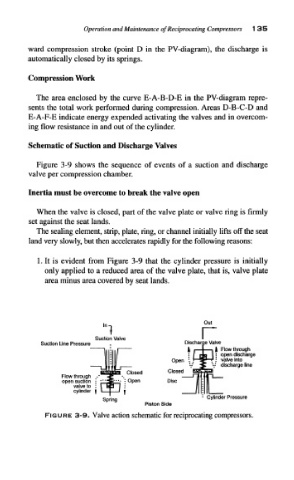
Schematic of Suction and Discharge Valves
Figure 3-9 shows the sequence of events of a suction and discharge
valve per compression chamber.
Inertia must be overcome to break the valve open
When the valve is closed, part of the valve plate or valve ring is firmly
set against the seat lands.
The sealing element, strip, plate, ring, or channel initially lifts off the seat
land very slowly, but then accelerates rapidly for the following reasons:
1. It is evident from Figure 3-9 that the cylinder pressure is initially
only applied to a reduced area of the valve plate, that is, valve plate
area minus area covered by seat lands.
in1 Out
Suction Valve I r
in Valve
Suction Line Pressure Discharge Valve
i Flow through
• open discharge
1
: valve into
V discharge line
Flow through ..•
open suction • ^j
valve to :
cylinder f
Cylinder Pressure
Piston Side
FIGURE 3-9. Valve action schematic for reciprocating compressors.