
Page 211 - Reciprocating Compressors Operation Maintenance
P. 211
Operation and Maintenance of Reciprocating Compressors 1 97
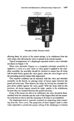
FIGURE 3-53. Pressure switch.
allowing them, by action of the return springs, to be withdrawn from the
valve strips, thus allowing the valve to operate in its normal manner.
Typical arrangements of a diaphragm-operated suction valve unloader
are shown in Figure 3-54.
When new unloader fingers or a complete unloader assembly is
applied to a valve or a new valve or valve guard is applied to the com-
plete assembly, the assembly should be checked to ensure that all strips
will be held firmly against the valve guard, when the valve fingers are in
the unloading position (strips fully depressed).
This required condition can be checked, with the valve and unloader
assembly on the bench, by placing strips of tissue paper between the
guard and each strip. Then depress the strips, by forcing the unloader fin-
gers down solidly against the valve guard. With the strips held in this
position, all tissue papers should be tight, unable to be withdrawn,
because they are clamped between the guard and strips.
If any of the tissues are able to be withdrawn, the valve should be disas-
sembled from the unloader and the ends of the fingers filed and the assem-
bly rechecked as above until the clamping of all strips is accomplished.
The diaphragm head is typically mounted on supporting studs extend-
ing from the valve cover. The projection of these support studs is often
made adjustable to permit the proper setting of the diaphragm in relation