
Page 215 - Reciprocating Compressors Operation Maintenance
P. 215
Operation and Maintenance of Reciprocating Compressors 201
FIGURE 3-55. Three-step control panel.
suction valves
crank ^ _ ,
end rf t\ «n<*
discharge valves
50% capacity 0 capacity
100% capacity (suction valves held (suction valves held
open crank end) open both ends)
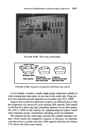
FIGURE 3-56. Sequence of operation with three-step control.
As an example, consider a simple single-acting compressor cylinder in
which compression takes place on one end of the stroke only. Using suc-
tion valve unloaders permits operation at two points only, 0% or 100%.
Suppose that a particular application requires an additional step so that
the compressor can operate at a point offering 50% capacity. This control
would then be a three-step type, permitting operation at any three points,
0%, 50% or 100% of full capacity. By supplementing the bypass control
with a clearance pocket, intermediate unloading can be accomplished.
The clearance pocket, when open, increases the cylinder clearance vol-
ume, which causes the compressor capacity to decrease. An indicator
card taken from a cylinder end with a 50% capacity reduction (see Figure
3-57) shows this effect more clearly.