
Page 219 - Reciprocating Compressors Operation Maintenance
P. 219
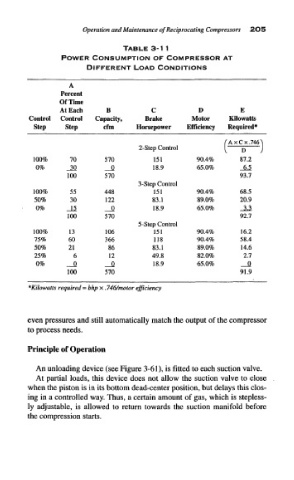
Operation and Maintenance  of Reciprocating  Compressors  2O5

                                   TABLE 3-1 l
                  POWER    CONSUMPTION     OF  COMPRESSOR AT
                         DIFFERENT    LOAD CONDITIONS

                    A
                  Percent
                  Of Time
                  At Each     B            C           D           E
         Control  Control  Capacity,     Brake        Motor     Kilowatts
           Step    Step       cfm      Horsepower   Efficiency  Required*
                                                              (  AxCx.746^
                                       2-Step Control
                                                              1    D    J
           100%      70       570          151         90.4%       87.2
           0%       _JQ       _JQ          18.9        65.0%       _M
                    100       570                                  93.7
                                       3-Step Control
           100%      55       448          151         90.4%       68.5
           50%       30       122          83.1        89.0%       20.9
           0%       Jl        _Q           18.9        65.0%       JL2
                    100       570                                  92.7
                                       5-Step Control
           100%     13        106          151         90.4%       16.2
           75%      60        366          118         90.4%       58.4
           50%      21         86          83.1        89.0%       14.6
           25%        6        12          49.8        82.0%        2.7
           0%         0       __Q          18.9        65.0%       _Q
                    100       570                                  91.9
         *Kilowatts  required = bhp x. 746/motor  efficiency


         even pressures  and still automatically  match the output of the compressor
         to process  needs.

         Principle of Operation


           An unloading device  (see  Figure 3-61), is fitted  to each  suction valve.
           At  partial  loads, this  device does  not allow  the  suction  valve  to close
         when the piston is in its bottom dead-center  position,  but delays this clos-
         ing  in a controlled  way. Thus, a certain amount of gas,  which is stepless-
         ly  adjustable,  is  allowed  to  return  towards  the  suction  manifold  before
         the compression starts.