
Page 218 - Reciprocating Compressors Operation Maintenance
P. 218
2O4 Reciprocating Compressors: Operation and Maintenance
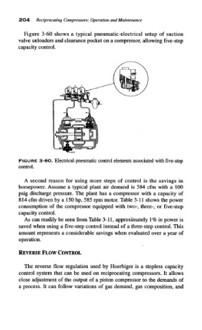
Figure 3-60 shows a typical pneumatic-electrical setup of suction
valve unloaders and clearance pocket on a compressor, allowing five-step
capacity control.
FIGURE 3-6O. Electrical-pneumatic control elements associated with five-step
control.
A second reason for using more steps of control is the savings in
horsepower. Assume a typical plant air demand is 584 cfm with a 100
psig discharge pressure. The plant has a compressor with a capacity of
814 cfm driven by a 150 hp, 585 rpm motor. Table 3-11 shows the power
consumption of the compressor equipped with two-, three-, or five-step
capacity control.
As can readily be seen from Table 3-11, approximately 1% in power is
saved when using a five-step control instead of a three-step control. This
amount represents a considerable savings when evaluated over a year of
operation.
The reverse flow regulation used by Hoerbiger is a stepless capacity
control system that can be used on reciprocating compressors. It allows
close adjustment of the output of a piston compressor to the demands of
a process. It can follow variations of gas demand, gas composition, and