
Page 233 - Reciprocating Compressors Operation Maintenance
P. 233
218 Reciprocating Compressors: Operation and Maintenance
The following section discusses some actual operating data on mainte-
nance expenses, downtime events, availabilities, and spare-parts con-
sumption for labyrinth-piston compressors. It also outlines the routine-
maintenance program followed by one plant that has had particularly
good experience with these units.
Labyrinth-piston compressors, as illustrated in Figures 3-65 and 3-66,
have labyrinth grooves machined in the periphery of the piston and in the
cylinder wall, and a similar labyrinth tooth design between the piston rod
and packing gland. A so-called "distance piece," which is a space that
may be either open to the atmosphere or closed (see Figure 3-66), sepa-
rates the oil-free compression space from the lubricated crankcase. Four
designs are typically available, as shown.
The grooves in the piston and cylinder rod provide a contactless seal
between those parts. The seal is made up of a large number of throttling
points and volume chambers arranged in series. Each throttling point acts
as a small orifice, where pressure energy is transformed into kinetic ener-
gy. The gas velocity then decreases in the subsequent volume chamber,
and the kinetic energy is transformed into heat and vortex energy. This
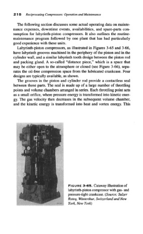
FIGURE 3-65. Cutaway illustration of
labyrinth-piston compressor with gas- and
pressure-tight crankcase. (Source: Sulzer
Roteq, Winterthur, Switzerland and New
York, New York)