
Page 245 - Reciprocating Compressors Operation Maintenance
P. 245
23O Reciprocating Compressors: Operation and Maintenance
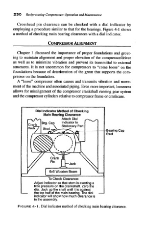
Crosshead pin clearance can be checked with a dial indicator by
employing a procedure similar to that for the bearings. Figure 4-1 shows
a method of checking main bearing clearances with a dial indicator.
^ COMPRESSOR ALIGNMENT
Chapter 1 discussed the importance of proper foundations and grout-
ing to maintain alignment and proper elevation of the compressor/driver
as well as to minimize vibration and prevent its transmittal to external
structures. It is not uncommon for compressors to "come loose" on the
foundations because of deterioration of the grout that supports the com-
pressor on the foundation.
A "loose" compressor often causes and transmits vibration and move-
ment of the machine and associated piping. Even more important, looseness
allows for misalignment of the compressor crankshaft running gear system
and the compressor cylinders relative to compressor frame or crankcase.
Dial Indicator Method of Checking
Main Bearing Clearance
**-v/V-* Attach Dial s~^ ^
\f
^*~r
Crank Brg. Cap Indicator to
\ Stationary Part
C) nH X ^
/ "^^^^.ftrH -Bearing Cap
Stud
sS^v "" % % \
/ / $
//$>X>^/' » 1
\^ I /'
KN>OsXN?l
y
/ Crank fi i \
^
6x6 Wooden Beam \
/
-n
To Check Clearance: 1
Adjust indicator so that stem is exerting a
little pressure on the crankshaft. Zero the
dial. Jack up the shaft until it is against
the top half of the main bearing. The dial —
indicator will show how much clearance is
in the assembly.
FIGURE 4-1. Dial indicator method of checking main bearing clearance.